Canadian Capacity Guide for Signalized Intersections (CCG)
The Traffic Control table for the CCG methods for signals is shown in the figure of the table below.
Table definitions are presented in the table below the figure Traffic Control: CCG for Signalized Intersections Table. Common parameters are described in a separate chapter (see section Common Parameters and Unknown Control Type).
Figure 15: Traffic Control: CCG for Signalized Intersections Table
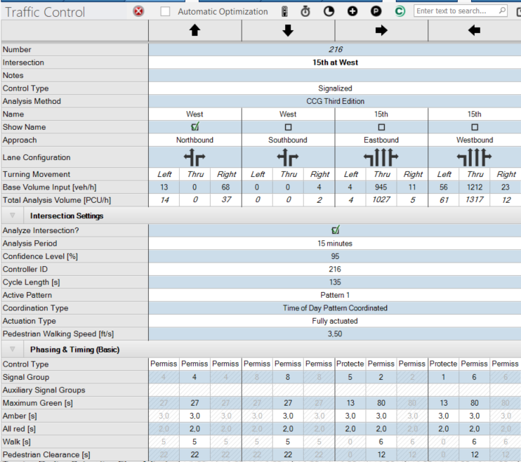
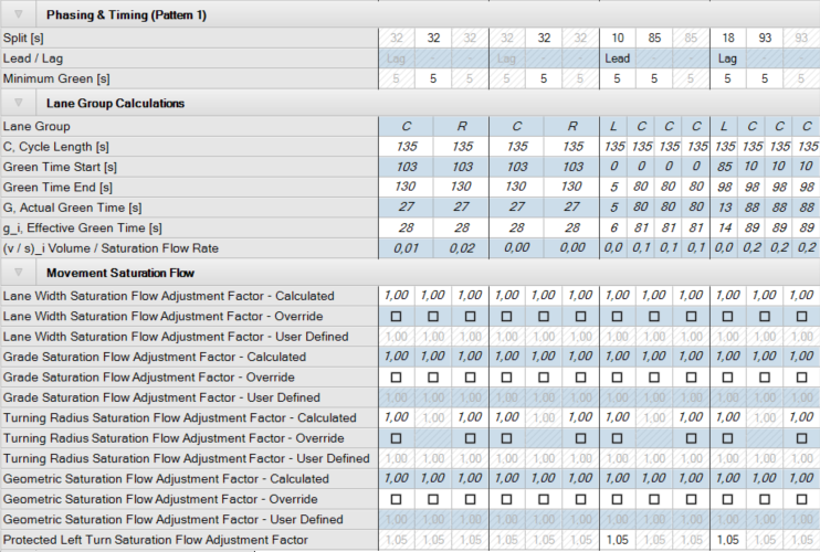
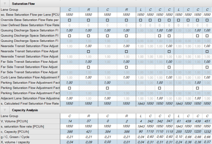
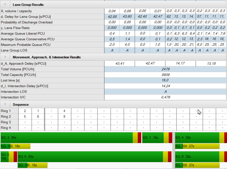
Table 20: Traffic Control Parameters: CCG for Signalized Intersections
| Parameter | Description | Units |
|---|---|---|
|
Intersection Settings |
||
|
Analyze Intersection? |
A check box indicates this intersection will be included in the reports. |
|
| Analysis Period | Time period for the analysis, either 15 min, utilizing the peak 15-min flow multiplied by 4 assigned by the PHF, or 1 hr, ignoring the PHF. | |
| Confidence level | Confidence level [%] Default value 95 % | |
| Controller ID |
Each signal controller has a unique ID number. This value defaults to the intersection number, but can be changed for intersections that are controlled by a controller common to another intersection. To edit default Controllers IDs to another number or specialized agency number systems open the Edit Controller window under Signal Controller >Edit Controllers. This window allows for editing traffic signal controller IDs and provide a description. This shows the intersection and coordination groups assigned to the controller. |
|
|
Cycle Length |
Controller cycle length. This is the maximum time it will take for each signal group to cycle once. The cycle length is only used for coordination. |
s |
| Coordination Type | Defines coordination as Free, Time of Day Pattern Coordinated, or Time of Day Pattern Isolated. |
|
| Actuation Type |
Defines whether the controller operates as:
|
|
|
Phasing & Timing |
||
|
Control Type |
Defines control of movements as:
|
|
|
Signal Group |
The signal group is the signal phase number. |
|
|
Auxiliary Signal Groups |
All signal groups serving the movement. When the Control Type is Overlap and the Signal Group for the Overlap phase is entered, the Auxiliary Signal Groups cell is active and allows selections of all phases this movement overlaps with. |
|
|
Lead/Lag |
Selection for Lead or Lag left turn for protected phasing. |
|
| Minimum Green | Minimum Green time that the signal group will serve before changing to yellow. | s |
| Maximum Green |
Maximum time that the signal group will be allowed extend before it will max-out. A max-out will make a signal group eligible to terminate, even though it may not have gapped out. This parameter when exported via the Vissim (ANM) export to RBC is reflected as Max1. Editing the Split, Amber, All red, or Delayed Vehicle Green the Maximum Green time is automatically adapted, if the signal group satisfies the consistency conditions in all patterns. This implies that the Split is the same in all patterns. |
|
| Amber | Time a signal group will time an amber interval before advancing to red. | |
| All red | Time a signal group will time red before a conflicting signal group will be allowed to begin timing. | |
|
Lane Group Calculations |
||
| Lane Group | Lane or group of lanes designated for analysis | |
| C, Cycle Length | Controller cycle length. This is the maximum time it will take for each signal group to cycle once. The cycle length is only used for coordination. | s |
| Green time Start | Start of the signal group green time in the local cycle. | s |
| Green time End | End of the signal group green time in the local cycle | s |
| g_i, Effective Green Time | Amount of green time where vehicles proceed at the saturation flow rate | s |
| (v / s)_i Volume / Saturation Flow Rate | The ratio of the effective green time of a signal group to the saturation flow rate. | s |
|
Movement Saturation Flow |
||
| Lane width Saturation Flow Adjustment Factor - Calculated | Adjustment factor for the lane width saturation flow, Default = 1 | s |
| Lane width Saturation Flow Adjustment Factor - Override | Checkbox to activate user input for lane width saturation flow adjustment | |
| Lane width Saturation Flow Adjustment Factor – User Defined | User defined Lane width saturation flow adjustment factor | s |
| Grade Saturation Flow Adjustment Factor - Calculated | Adjustment factor for the grade saturation flow, Default = 1 | s |
| Grade Saturation Flow Adjustment Factor - Override | Checkbox to activate user input for grade saturation flow adjustment | |
| Grade Saturation Flow Adjustment Factor - User Defined | User defined grade saturation flow adjustment factor | s |
| Turning Radius Saturation Flow Adjustment Factor - Calculated | Adjustment factor for the turning radius saturation flow, Default = 1 | s |
| Turning Radius Saturation Flow Adjustment Factor - Override | Checkbox to activate user input for turning radius saturation flow adjustment | |
| Turning Radius Saturation Flow Adjustment Factor - User Defined | User defined turning radius saturation flow adjustment factor | s |
| Geometric Saturation Flow Adjustment Factor - Calculated | Adjustment factor for the geometric saturation flow, Default = 1 | s |
| Geometric Saturation Flow Adjustment Factor - Override | Checkbox to activate user input for geometric saturation flow adjustment | |
| Geometric Saturation Flow Adjustment Factor - User Defined | User defined geometric saturation flow adjustment factor | s |
| Protected Left-Turn Saturation Flow Adjustment Factor | Adjustment factor for the protected left-turn saturation flow | s |
|
Saturation Flow |
||
|
Lane Group |
Lane or group of lanes designated for analysis |
|
|
so, Base Saturation Flow per Lane |
Base saturation flow rate |
PCU/h/ln |
| Override Base Saturation Flow per Lane | Checkbox to activate user defined base saturation flow per lane | |
| User defined Base Saturation Flow per Lane | User defined base saturation flow per lane | PCU/h/ln |
| Queuing Discharge Space Saturation - Calculated | Calculated queuing discharge space saturation, Default = 1 | |
| Queuing Discharge Space Saturation - Override | Checkbox to activate user defined queuing discharge space saturation | |
| Queuing Discharge Space Saturation - User defined | User defined queuing discharge space saturation | |
| Nearside Transit Saturation Flow Adjustment Factor - Calculated | Adjustment factor for the nearside transit saturation flow, Default = 1 | |
| Nearside Transit Saturation Flow Adjustment Factor - Override | Checkbox to activate user defined nearside transit saturation flow adjustment | |
| Nearside Transit Saturation Flow Adjustment Factor - User defined | User defined nearside transit saturation flow adjustment | |
| Far Side Transit Saturation Flow Adjustment Factor - Calculated | Adjustment factor for the far side transit saturation flow, Default = 1 | |
| Far Side Transit Saturation Flow Adjustment Factor - Override | Checkbox to activate user defined far side transit saturation | |
| Far Side Transit Saturation Flow Adjustment Factor - User defined | User defined far side transit saturation | |
| Curb Lane Saturation Flow Adjustment Factor - Calculated | Adjustment factor for the curb lane saturation flow | |
| Parking Saturation Flow Adjustment Factor - Calculated | Adjustment factor for the parking saturation flow | |
| Parking Transit Saturation Flow Adjustment Factor - Override | Checkbox to activate user defined parking transit saturation | |
| Parking Transit Saturation Flow Adjustment Factor - User defined | User defined parking transit saturation | |
| Adjacent Lane Saturation Flow Adjustment Factor - Calculated | Adjustment Factor for the adjacent lane saturation flow | |
| s, Calculated Final Saturation Flow rate | Calculated final saturation flow rate after all adjustments has been taken into account. | PCU/h |
|
Capacity Analysis |
||
| Lane Group | Lane or group of lanes designated for analysis | |
| V, Volume | Lane group volume (total analysis volume) | PCU/h/ln |
| s, saturation flow rate | Final saturated flow rate (ca) | PCU/h |
| C, Capacity | Effective capacity | PCU/h |
| g / C, Green / Cycle | The ratio of the effective green time of a signal group to the cycle length | |
| X. volume / capacity | The ratio of the total analysis volume (flow rate) to the capacity | |
|
Lane Group results |
||
| X. volume / capacity | The ratio of the total analysis volume (flow rate) to the capacity | |
| D, Delay for lane group | Control delay for lane group | s/PCU |
| Probability of Discharge Overload | Probability of discharge overload | |
| y, Lane Flow Ratio | Lane flow ratio | |
| Average Queue Liberal PCU | Average queue conservative | |
| Maximum Probable Queue PCU | Maximum probable queue | |
| Lane Group LOS | Level-of-service for lane group | |
|
Movement, Approach, & Intersection Results |
||
| D_A Approach Delay | Average control delay by approach |
s/PCU |
| Total volume | Total volume |
PCU/h |
| Total capacity | Total capacity |
PCU/h |
| Lost time | Lost time | |
| D_I, Intersection delay | Average control delay for intersection | |
|
Intersection LOS |
Level-of-service for the intersection |
|
|
Intersection V/C |
Volume-to-capacity ratio for the intersection |
|
|
Sequence editor |
||
| Ring 1 | User defines the Signal Groups that occur in Ring 1 | |
| Ring 2 | User defines the Signal Groups that occur in Ring 2, if applicable | |
| Ring 3 | User defines the Signal Groups that occur in Ring 3, if applicable | |
| Ring 4 | User defines the Signal Groups that occur in Ring 4, if applicable | |
