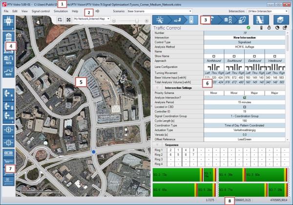
The Vistro software User Interface contains the following (see Figure 1: Vistro Interface):
|
Element |
Description |
|
(1) Header |
Shows the Program Title, Version, Service Pack number, and Network Filename; for demo versions, “Demo” is added to the version number. |
|
(2) Menu Bar |
Contains drop-down menus, undo/redo shortcuts, scenario selector, intersection selector and the Vissim previewer. |
|
(3) Workflow Panel |
Contains the tabs for data entry and analysis for various stages of the project workflow. A search field allows the current table to be filtered to a search item. |
|
(4) Toolbar |
Contains the tools for adding network objects. |
|
(5) Network Window |
Displays the currently opened network, including the background map / image and representation of the roadway geometry. In this window, you can build and edit the network structure graphically, using the items from the Toolbar, as described inNetwork BuildingNetwork Building. You can also move and adjust the display using the zoom and windowing tools, as well as the measuring tool. |
|
(6) Data Window |
In this window, data is shown for the relevant task button selected. This will reflect associated data tables and functions specific to each task. Selection of a workflow Task Button results in the display of the related workflow table in the Data Window. |
|
(7) Graphics Selector |
Contains various graphical displays for the network window. |
|
(8) Status Bar |
Displays:
|
 (current scale ratio display of the Network Area)
 (x-y coordinates of the mouse location in the Network Area) using gthe Spherical Mercator coordinate system.