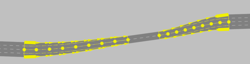
Modeling connectors
In order for vehicles to continue their journey on the following links, you must connect these links with connectors. This also allows you to model turn relations at junctions.
Connectors can only be inserted between two links. You cannot connect connectors to each other.
You can also model inside merges accordingly, for example to reduce the number of lanes downstream of managed lanes facilities. Modeling allows one or several lanes to be located between the outer lanes, if they have not to-links. Lanes that start between the outer lanes disappear until the end point of the connector.
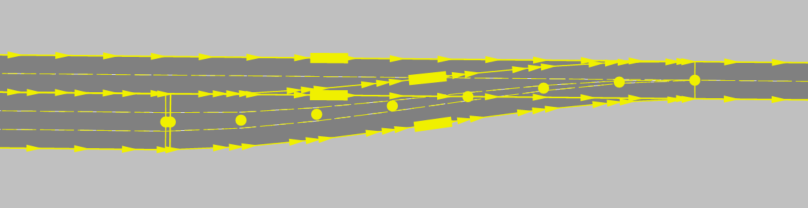
Lanes cannot cross each other in connectors.
When using vehicle routes, make sure that through traffic follows vehicle routes that extend beyond the connector onto the lanes of the corresponding link. This particularly applies to lane reductions.
Connectors have attributes and options which are largely comparable to those of links (Attributes of connectors), (Attributes of links).
You may move the start or end point of a connector to a different link later on.
Vissim automatically inserts connectors when you create a car park (Creating a car park).
|
|
Tips: You will find sample data and a description in your Vissim installation: ..\Examples Training\Merging & Weaving You will find the following tutorials on modeling connectors on the PTV Mobility Youtube channel of PTV GROUP |

