Presetting vehicle attributes in FBX 3D model file
When adding a 3D model file *.fbx to a 2D/3D model segment, Vissim can import doors and material groups from the file.
If the software used to edit the *.fbx file allows for custom properties, you can define a property for the height of the walkable ground in a PT vehicle. Upon import, Vissim automatically assigns this property’s value to the zOffset attribute of the 3D model segment.
To enable Vissim to read this data, edit the *.fbx file before adding the file to Vissim. For this purpose, select the program you use to create the *.fbx file, for example ![]() Blender.
Blender.
Configuring doors in the *.fbx file
Depending on the program you are using, you have the following options for marking nodes under the 3D scene in the *.fbx file that Vissim is to read in as a door.
Option 1:
- ► Name the node Vissim door.
Option 2: if the program allows you to create and name attributes on nodes under the 3D scene:
- ► Create the Vissim door attribute for the node and enter a value > 0 if you want to activate the door.
If you want to deactivate the door, enter a value <= 0.
Do not continue to apply this method in order to edit other nodes that lie below a Vissim door node in the structure of a 3D scene and thus belong to it. These nodes cannot define another door.
Configuring material groups in the *.fbx file
Depending on the program you are using, you have the following options for marking material groups, turning indicators and brake lights in the *.fbx file that Vissim reads in.
Option 1:
- ► Based on the following table, enter the material name.
Option 2, if the program allows you to create and name attributes:
- ► Create the following attributes in the *.fbx file and enter the values below:
|
Group in Vissim |
Material name |
Attribute and value in *.fbx file |
|
Color group 1 |
Vissim color group 1 |
Vissim color group Value: 1 |
|
Color group 2 |
Vissim color group 2 |
Vissim color group Value: 2 |
|
Color group 3 |
Vissim color group 3 |
Vissim color group Value: 3 |
|
Color group 4 |
Vissim color group 4 |
Vissim color group Value: 4 |
|
Turning indicator, left |
Vissim indicator left |
Vissim indicator left Value: > 0 |
|
Turning indicator, right |
Vissim indicator right |
Vissim indicator right Value: > 0 |
|
Brake lights |
Vissim brake lights |
Vissim brake lights Value: > 0 |
|
ZOffset |
Vissim Floor ZOffset |
Vissim brake lights Value: > 0 |
Specifying zOffset for floor height of a PT vehicle in *.fbx file
In Vissim, the height of the walkable floor of a public transport vehicle, where passengers board and alight in 3D mode, is defined by the ZOffset attribute. When you import a 3D model file *.fbx, this value is automatically set to match the height of the bottom edge of the corresponding door object in the 3D model. If the bottom edge in the 3D model file is lower than the walkable floor height, you can set the zOffset value as a custom property, such as Vissim Floor ZOffset, depending on the editing software used. Vissim will then use the value from Vissim Floor ZOffset for the ZOffset attribute.
Naming objects and specifying the object type in the *.fbx file
The objects you add to Blender are of the type Empty. Depending on the Vissim attribute, you determine whether the object is to be displayed as Cube or Sphere. After having added Cube or Sphere, you must name this object according to specifications in the following table:
|
Attribute in Vissim |
Name of the object in the FBX file |
Object Empty |
|
Dimensions length, width, height |
Vissim Dimensions |
Cube |
|
Front axle |
Vissim Axle Front |
Cube |
|
Axle (rear) |
Vissim Axle Rear |
Cube |
|
Joint position (front) |
Vissim joint (front) |
Cube |
|
Joint position (rear) |
Vissim Joint Rear |
Cube |
|
Shaft length |
Vissim Shaft End |
Sphere |
|
Section between Part without passengers (front) and Part without passengers (rear) |
Vissim Passenger Area |
Cube |
In the properties of each cube and the Sphere object, enter the desired attribute values. When adding the 3D model file *.fbx, Vissim can now assign these values to the corresponding Vissim attributes of the 2D/3D model segment and display the vehicle geometry based on these values. You can view the attribute values in the 2D/3D model segments (Attributes of 2D/3D model segments) list and display them in the Edit 2D/3D model window (Defining 2D/3D models).
The following instructions describe how to perform these steps in Blender 2.3.3 (English user interface).
Creating, naming and entering cubes and Sphere for Vissim vehicle attributes
1. Open the 3D model of the vehicle in Blender.
2. Zoom until the 3D model is fully displayed.
3. Align the 3D model horizontally with the direction of travel to the left, example:

Follow the steps below to insert a cube and enter the attribute values. Perform these steps one after the other for each cube of the different attributes as well as for the Sphere object of the Shaft length attribute. First, specify the position of the cube or the Sphere object in the model. In this example, this is the Vissim Dimensions cube that you use to define the dimensions length, width, height.
4. Click the  Cursor.
5. For the Vissim Dimensions cube, click in the center of the model:
|
For notes on the position of the cubes of the other attributes as well as the Sphere object for the shaft length, see the table below (Positions of the cubes and the Sphere object in the FBX model).
A cursor marker is added to the position you clicked. In the next step you define the type of the object depending on the attribute:
- ► For Vissim Dimensions or Vissim Axle Front, Vissim Axle Rear, Vissim Joint Front, Vissim Joint Rear, Vissim Passenger Area, on the menu Add, click > Empty > Cube.
- ► For Vissim Shaft End, on the menu Add, click > Empty > Sphere.
A wireframe cube is displayed.
6. Click  Object Data Properties and as Size, enter: 1.0 meter
7. Click  Object Properties > Viewport Display and overwrite the name of the cube depending on the attribute it should represent in Vissim (Naming objects and specifying the object type in the *.fbx file). In this example: Vissim Dimensions.
8. Click Object Properties > Viewport Display and enable the Name option.
The name of the wireframe cube is shown in the context menu. This makes it easier to identify the object.
9. Click Object Properties > Viewport Display and enable the Axis option.
The x-axis, y-axis and z-axis are displayed on the wireframe cube. This makes it easier to align the network.
10. Go to Object Properties > Transform and check the model position specified in the boxes Location X, Y, Z.
For Vissim Dimensions, the scale must correspond to the dimensions of the model in meters. You can enter these as values.
11. Go to Object Properties > Transform and make sure that the correct model dimensions are entered in the boxes Scale X, Y, Z.
12. If the values do not correspond to those of the model, correct the values.
13. Save the model.
14. Follow these steps for all the attributes you want to add to Vissim using this model.
See figure below for a fully defined model in Blender:
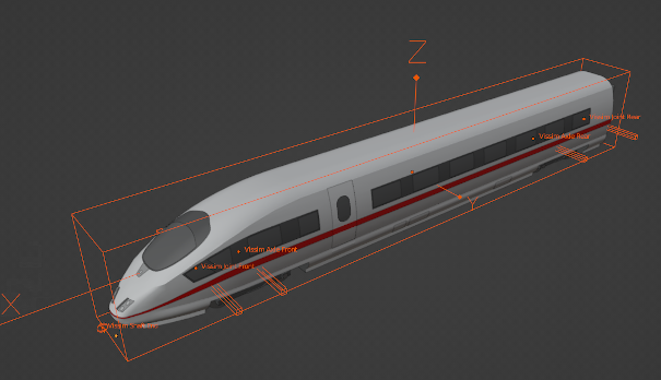
15. Export the model in the fbx file format.
Add the *.fbx file to Vissim (Defining 2D/3D models), (Attributes of 2D/3D model segments).
Positions of the cubes and the Sphere object in the FBX model
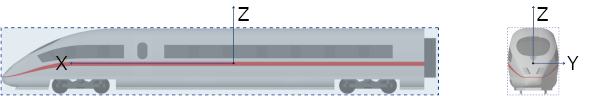
The graphics in the following table show the positions of the cubes and theSphere object based on the X, Y, Z axes.
- For the Vissim Dimensions and Vissim Passenger Area cubes, the area defined by the attribute values is displayed.
- For the cubes of the axis positions, the joint positions and for the Sphere object of the Shaft Length attribute, the distance to the front edge defined by the attribute values is displayed.
|
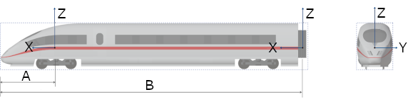
The cursor for the Cube Vissim Dimensions is positioned in the center of the model. The attributes of the cube define its size from the front edge to the rear edge and the width of the model. This is shown by the area within the dashed frame line:
|
|
|
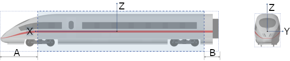
The cursor for the Vissim Passenger Area cube is positioned in the center of the model. The attributes of the cube define its size for the section between the Part without passengers (front), in the figure: A, and the Part without passengers (rear), in the figure: B:
|
|
|
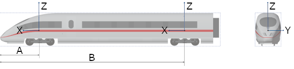
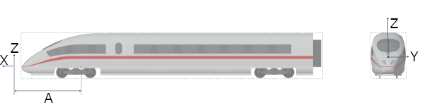
The cursors for the cubes of the axis positions are positioned in the center of the axes. The attributes of the cubes indicate the correct distance to the front edge. The front edge is defined by the dimensions in the Vissim Dimensions cube.
|
|
|
The cursors for the cubes of the joint positions are positioned in the center of the axes. The attributes of the cubes indicate the correct distance to the front edge. The front edge is defined by the dimensions in the Vissim Dimensions cube.
|
|
|
The cursor for the Sphere object for the shaft length is positioned in front of the model’s front edge. The Sphere attributes indicate the distance to the joint position. The Vissim Shaft End Sphere for the attribute Shaft Length, in the figure A:
|
Superordinate topic:
