RBC Editor - Overview
Menu File
|
Opens a blank PRBC supply file. If signal groups are assigned to the existing controller in the window when creating a new file, and the signal groups are not recreated within the new controller, signal group information for signal head network objects may be lost. |
|
|
Imports a previously defined PRBC supply file. If signal groups are assigned to the existing controller in the window when importing a file, and the signal groups are not contained within the imported controller, signal group information for signal head network objects may be lost. |
|
|
Undo changes and revert to initial version. |
|
|
Save your PRBC supply file with the defined name. When creating a new signal controller you must save your RBC supply file before exi ting, if you want to use the signal timings defined in the interface. After the file has been saved with a name, any signal timing changes can be saved by clicking OK in the dialog. When creating a new controller or changing the name of the signal controller PRBC supply file, save your Vissim input file, otherwise the Vissim input file will not use the new PRBC supply file when reopened. |
|
|
Defines whether or not only the items selected in the tree view will be printed and be displayed within the Print Preview. |
|
| Prints your signal timing information to your desired printer. If Print Selected in the menu is checked, only the items selected in the tree view will be printed. | |
| Allows you to view the document that will be printed. There are no options for configuration within this dialog. If Print Selection in the menu is checked, only the items selected in the tree view will be shown. | |
| Exits the editor without saving the PRBC supply file. |
Menu View
|
Basic View |
Opens a default basic view settings file, hiding advanced controller features. These hidden features can be shown again by selecting them for display in the tree view. |
|
Selects exactly those attributes for display which have some non-default value in the current supply. |
|
|
Opens and closes the tree view table selection window. |
|
|
Opens and closes the message panel window. When the panel is closed, you can still expand the window, but when it is not expanded you will no longer see the message panel with the tabs with the number of errors, warnings, and messages. |
|
|
Save the state of your editor to an RBC settings (*.ini) file. These settings can be used by any RBC editor. This does not change nor save any signal timing values, only the editor display. |
|
|
Loads the controller display settings (*.ini) file that was previously saved. This does not change nor loards any signal timing values, only the editor display. |
Menu Help
|
Help |
Opens a browser and displays the Using RBC help topic of the Vissim Help. |
|
Input Fields
|
This field is not used by the controller or Vissim. It provides a way to store information within the controller file. |
|
|
Determines how many times per second the controller will communicate with Vissim during the simulation. During the communication information about detector calls are passed to the controller and the signal heads indications green, red, amber can be changed. |
Selection Panel

Tree View
Layered explorer tree for multi-selection of data groups. The options checked in this view will be shown in the Tables. This is for display purposes only. All data selection layout will be saved in RBC settings (*.ini) file. The items selected will affect the Print and Print Preview if the menu item Print Selected is checked.
Pattern Global
This table allows you to define global values for each pattern.
Selecting a different pattern
- ►
Right-mouse click on the pattern number within the Tree Panel.
The pattern shown in this table will define which pattern is displayed in the timing diagram.
Global Values
This table allows you to define global values for the signal controller.
Tables
This is the Graphical User Interface (GUI) for signal timing data entries. Only items selected within the tree view will be shown in the tables.

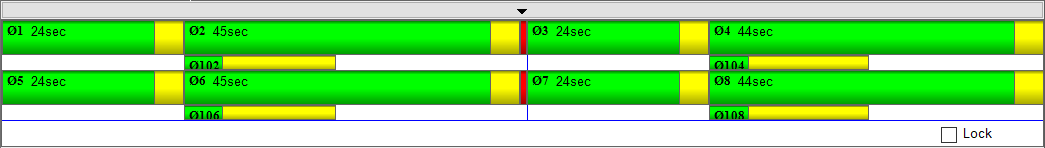
Timing Diagram
The Timing diagram gives you the ability to view and modify sequence and timing plans through a graphical interface. The timing diagram will display the timing defined within the pattern shown in the pattern global table.
If a pattern is selected, the split values will be modified. If free running is selected, the maximum green times will be modified.
Displaying the Base Timing, Free Running Timing
- ► Right-mouse click on the item base timing within the tree view.
Changing the Timing
- ► Drag within this Timing Diagram.
Locking the Diagram
The option Lock allows you to lock the diagram such that clicking within the timing diagram will no longer change the timing.
Log Panel
During editing potential risk situations will be checked for and if found they will be logged in the Log panel for review.
The logs for errors and warnings get updated automatically when the problem has been resolved. However, the messages continue to accumulate for the length of the session.

- The Errors table lists errors in the current supply that will prevent the simulation from starting.
- The Warnings table lists warnings about the current supply. Starting a simulation will not fail due to warnings, but the controller behavior may be unexpected.
- The Messages table lists other logged messages regarding the current session.
