RBC Definitions
Base Timing
Timing by SG: Basic
|
The signal Group used for identifying the signal group within the controller. This number is also used for the corresponding signal group object in Vissim. The signal group numbers assigned within a signal controller must be pairwise distinct. |
|
|
The SG name is only used within the RBC graphical interface. |
|
|
Defines the minimum green time for which the signal group must remain green after turning green. Min Green must be greater than 0. |
|
| The allowed time between extension calls before a signal group will gap out. Veh Extension is also known as the passage time. | |
|
Defines the maximum green time that the signal group will be allowed to extend before it will max-out. A max-out will make a signal group eligible to terminate, even though it may not have gapped-out. Normally, the maximum green timer will not begin counting until an opposing call to the signal group is present. If no opposing call is present the maximum green timer will be reseted. An exception to this rule is when the signal group is a flagged as a Max Recall signal group, in which case the maximum green timer will begin counting as soon as the signal group changes to green. Max 1 is the default maximum green time for each signal group. |
|
|
The time a signal group will remain an amber interval before advancing to red. This time cannot be abbreviated by any operation. |
|
|
The time a signal group will remain red before a conflicting signal group will be allowed to begin timing. |
|
|
The number of the pedestrian signal group associated with the vehicle signal group defined in the column. If no Ped SG Number is specified, no pedestrian SG will be associated with that vehicle SG. If specified, the Ped SG Number is also used for the corresponding signal group object in Vissim. The signal group numbers assigned within a signal controller must be pairwise distinct. |
|
|
The minimum time a signal group will display a walk indication before advancing to the pedestrian clearance interval (FDW). The associated vehicle SG must remain green while the pedestrian SG is in the walk interval. This parameter is ignored if no Ped SG Number is specified. |
|
|
The time a signal group will display a flashing don’t walk indication before advancing to solid don’t walk. The associated vehicle SG must remain green while the pedestrian SG is in the FDW interval. This parameter is ignored if no Ped SG Number is specified. |
|
|
Signal groups that will be green at the start of the simulation. By default, these signal groups will begin timing in green with walk if there is pedestrian timing defined. The signal groups flagged as Start Up must not be conflicting. If no signal groups are selected for Start Up, the first signal groups listed in the sequence will start in green at the start of the simulation. |
|
|
Signal groups flagged for this option will receive an automatic vehicle call. |
|
|
Signal groups flagged for this option will receive an automatic vehicle call and extension. The maximum green timer will unconditionally begin timing at the beginning of green. Without Max Recall, the maximum green timer will only time if there are opposing calls to the signal group. |
|
|
Signal groups flagged for this option will receive an automatic pedestrian call when they are not in walk. With Ped Recall, pedestrian signal groups only turn green together with their parent signal group. |
|
|
When a signal group is called in another barrier group, not all rings might have a signal group with a call in that same barrier group. In such rings, signal groups within that barrier group which are flagged as Dual Entry are considered called as well. This feature is often used for through-movement signal groups such that if one signal group is called, the opposite through movement is served as well. |
Timing by SG: Advanced
|
An alternate maximum green time for the signal group that can be used when the controller is running in a pattern. |
|
|
An alternate maximum green time for the signal group that is only observed if maximum timing is called for by a pattern. |
Pattern Global
A total of 7 patterns are available. If coordinated signal groups and a non-zero cycle length are defined in a pattern, the controller will run in coordinated mode, otherwise it will be in free-running mode. When the controller is in free-running mode, not all pattern variables are used. Variables that are not used in Free Running Mode are specified in the variable definitions. Any values set within patterns that are duplicates of variables within base timing override the base timing; zero values within a pattern are ignored. However, for those checkboxes which are duplicated, the pattern can only turn on checkboxes that are off in base timing. If they are on in base timing, they will still be on when the pattern is running.
|
The cycle length of the pattern is the maximum time it will take for each signal group to cycle once. The cycle length is only used for coordination. If a cycle length is not defined (set to zero), the pattern will run in Free Running Mode. If the cycle length is greater than zero, coordinated signal groups must be defined as well. |
|
|
When coordinated, the local cycle timer will be offset from the master cycle timer by the defined offset time. |
|
|
The Maximum Green Mode will be used for all signal groups while the coordination pattern is active. This selection is only valid for coordinated patterns; if used in Free Running Mode, the value will be ignored. The selections are:
|
|
|
The Permissive Mode for the coordination pattern controls the method in which permissive periods are opened and closed for all non-coordinated signal groups. The controller will only yield to signal groups that are permissive following the end of green on each coordinated signal group. The permissive modes are as follows:
The Permissive Period for non-coordinated signal groups will close:
If a signal group changes to green, the Permissive Period of the groups that sequentially follows considered as open, it is not necessary to wait until the appropriate Permissive Periods are opened. The Permissive Period for non-coordinated signal groups will close the same as they do for Single Band permissive operation above. |
|
|
During an active coordination pattern, activates explicit Force Offs defined in the pattern instead of using Splits. |
|
|
During an active coordination pattern using Explicit Force Offs defined in the pattern, activates Explicit Permissive Periods defined in the pattern instead of using automatically defined Permissive Periods. These can only be used with Explicit Force Offs. |
Patterns / Coordination
|
The split of a signal group is the amount of time allocated in the cycle for that signal group to time. The split includes the time it will take the green, amber, and red clearance intervals to time for each signal group. When using splits, force-off points, yield points and permissive periods are computed automatically. Force-off points and yield points are placed so that the signal group turns amber early enough within the cycle so that conflicting calls can be served at the start of their split. In many cases, the force-off point (or yield point) of a signal group will be placed just so that the signal group can serve its clearance before the end of its split. However, for signal groups placed just before the barrier, additional time might be required to cross the barrier, causing the force-off point to be placed earlier. This is required when the signal group might turn amber together with a signal group which has longer clearance time than the signal group itself. In that case, the longest relevant clearance time is used for computing the force-off point. |
|
| Example: Automatic force-off point computation with splits Consider a supply with the following sequence:
The cycle length is 60 s. Each signal group has a split of 15 s. Signal groups 2 and 6 are coordinated. The force-off point of SG4 is computed as follows:
Result: The force-off point of SG4 is placed at cycle second 55.
|
|
Conditions for Split values:Split values must satisfy the following conditions:
|
|
| Defines the minimum green time that a signal group will serve before changing to yellow. In the absence of any extension, the signal group will serve this minimum green time before it is eligible to terminate. This pattern minimum green time value will override values in the Basic timing when the pattern is running. If the value is set to zero within the pattern the controller will use the Min Green set in the Basic timing. | |
|
When defined for a signal group, this value overrides all maximum green times defined for this signal group when this pattern is running. This new max green time is used for both coordinated and free running patterns. |
|
|
If this is nonzero, it overrides the Veh extension value defined in the base pattern (Veh Extension). |
|
|
Defines the time in seconds measured past local zero point that selected green phase will end within local cycle. This value is only used if ExplicitForceOffs is set to On, otherwise automatic force offs are used as defined by Split and offset reference. |
|
|
This is the time period within the cycle in which a call for the signal group can be acknowledged by the controller and result in green time for that signal group if the call remains after prior signal groups with calls have cleared. This value is only used if both Explicit Force Offs and Explicit Permissives are set to On; otherwise, automatic permissive periods are used as defined by Permissive Mode. Permissive Period is defined by Permissive Start and Permissive End:
|
|
|
Signal groups that will observe Max 2 timing while the pattern is active. This setting is also used in Free Running Mode. |
|
|
Signal groups that will observe Max 3 timing while the pattern is active. If both Max 2 and Max 3 are selected for a signal group, Max 3 will be used. This setting is also used in Free Running Mode. |
|
|
In coordinated mode, the coordinated signal groups are used to introduce an element of fixed-time control into the cycle. They are automatically called and forced to be green during the green time allotted by their splits. Coordinated signal groups are typically the main street through signal groups of a street where vehicular progression is desired. If coordinated signal groups are not defined, the cycle length of the pattern must be 0 and controller will run in Free Running Mode. Otherwise, coordinated signal groups must all be defined in the same barrier group. Each ring which has signal groups in that barrier group must have a coordinated signal group. When using explicit force-offs, the yield point (that is, the cycle second in which the guaranteed green time of the coordinated signal group ends) of the coordinated signal group is the Force Off value configured in the pattern. |
|
|
see RBC Definitions (RBC Definitions). This will also be applied if the pattern is run in Free Running Mode. |
|
|
When the pattern Max Green Mode in pattern global setting is set to anything except for MaxInhibit, this parameter allows individual signal groups to be defined for MaxInhibit, i.e. ignore the signal group maximum green timer and only terminate by gap-out or force-off. |
Pattern Schedule
|
This is the pattern that will run starting at the defined Pattern Start Time. The Free Running Mode will run the Basic and Advanced timing. |
|
|
This is the start time in seconds from midnight, at which the defined pattern will start running. The simulation start time will be taken into account. If more than one pattern is defined for the same start time, the last listed will be the pattern that is run for that time. Active patterns will only end with another pattern begins. |
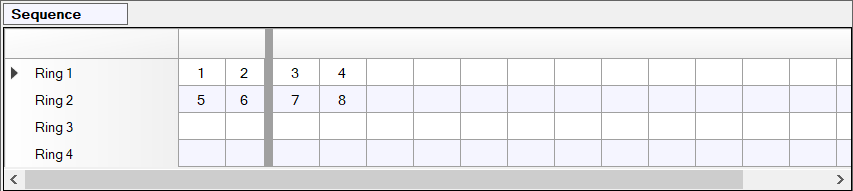
Sequence
This parameter defines which vehicle signal groups can time together.
The sequence consists of rings and barriers. Each row of this table represents a ring. A barrier can be inserted or removed to the right a column by double-clicking on the column header. Sections of the table between barriers are called barrier groups. Empty barrier groups are ignored by the controller.
Each vehicle signal group can be placed at most once in the sequence, while other kinds of signal groups (for example, pedestrian SGs) cannot be placed directly in the sequence.
If two signal groups are contained in the same barrier group and are placed in different rings, they are called compatible and can time together. Signal groups that are not compatible (placed in the same ring or separated by a barrier) are called conflicting and cannot time together.
If a vehicle signal group is omitted from the sequence, it cannot turn green.
Overlaps
|
Signal Group numbers for corresponding overlap. The signal group number that will be created in Vissim and will be used to create signal heads that used the timing defined for this overlap. |
|
| When a Parent signal group is flagged as a Delay Enable Signal Group is timing, the overlap will time this delay prior to changing from red to green. | |
| When a Parent signal group flagged as a Trail Enable Signal Group is timing, the overlap will time this green clearance (trailing green time) prior to changing amber. | |
| The time an overlap will display amber before advancing to red. This time cannot be abbreviated by any operation. | |
|
The time an overlap will display red before any signal groups that conflict with either the overlap or its Parent signal groups can begin timing. This time cannot be abbreviated by any operation. |
|
|
These are the signal groups that the overlap will be allowed to time with. When one parent signal group is timing and another parent signal group is next, the overlap will remain green (unless a negative vehicle or pedestrian signal group is next). When the last parent signal group terminates, the overlap will also terminate. |
|
|
An optional delay (Delay Green time) will be timed prior to the overlap changing from red to green if any signal group flagged for this option is timing. |
|
|
Normally when an overlap terminates, it will begin timing its amber clearance interval. An optional green clearance interval (Trail Green time) will be timed prior to the amber clearance interval if any signal group flagged for this option is timing. This is commonly used at intersections where an overlap controls a movement that cascades one or more signal groups and requires addition travel time from the movements controlled by the Parent signal groups. |
Global Values
These parameters are defined only once per signal controller and therefore are used for all patterns within the signal controller. These parameters only apply when coordination is used.
|
This is the point in the cycle where the master cycle timer will be equal to the defined offset time when the controller is coordinated and not in transition (offset seeking). The selections are:
|
Detectors
Vehicle
|
The detector number that should be used within Vissim to call or extend the vehicle signal groups selected. There are 64 available vehicle detectors. |
|
|
The amount of time that Extend signal group will be extended after the detector input is off. See Detector Mode for alternate uses of the Extend time for different modes. |
|
|
Signal Groups that are called when the detector input is on. |
Pedestrian
|
The detector number that should be used within Vissim to call the pedestrian signal groups selected. There are 16 available pedestrian detectors. |
|
|
This parameter defines the pedestrian signal groups that are called when the detector input is on. |
