Modeling nodes
The geometry of the road network is modeled in a very detailed manner in Vissim. This exactness is not necessary for the decision of a driver for a specific path through the network. The exact traffic routing at the node is not relevant; instead, the directions on the nodes which can be turned are relevant.
In order to reduce the complexity of the network model and therefore also the calculation time and memory required, you can identify parts of the network as nodes. These positions are at the minimum the positions in which the paths merge together, or the positions which branch out in different directions. Normally these are the network sections which represent a real intersection. Do not group larger network sections, containing multiple intersections, into a node.
Nodes for evaluations, dynamic assignment and mesoscopic simulation
In the attributes of the node, you select whether you want to use the node for evaluations and/or dynamic assignment and/or mesoscopic simulation. Depending on the particularities of the network, a node can be used for evaluations, dynamic assignment and mesoscopic simulation. However, certain particularities of a network might require you to model additional nodes for mesoscopic simulation (Mesoscopic node-edge model).
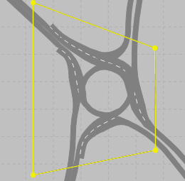
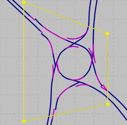
To perform dynamic assignment, you only need one node for each roundabout or complex intersection. For these nodes, select the attribute Use for dynamic assignment. It is not necessary to define a separate node for each conflict of two movements. Example file ..\Examples Demo\Roundabout Schenectady.US\Roundabout Schenectady.inpx:
Nodes at the boundary of a network
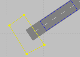
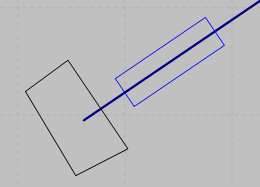
For dynamic assignment, nodes are required at the boundaries of the network where links in the Network editor begin or end. Example file ..\Examples Training\Dynamic Assignment \Detour\Detour.inpx:
|
|
Notes:
|

Superordinate topic:
Building an Abstract Network Graph
Information on editing:
Quick start dynamic assignment
Selecting nodes, polygons or segments
Related topics: