Open topic with navigation
Defining 2D/3D models
You can define 2D/3D models for vehicles and pedestrians with or without 3D model files. With 3D model files, the following file formats are supported:
| Format |
Model file |
|
*.3ds
|
Autodesk 3ds Max
|
|
*.dwf
|
Autodesk Design Web Format
|
|
*.v3d
|
Vissim 3D
|
|
*.skp
|
SketchUp
Vissimoffers advanced functionality if certain naming conventions are contained in the *.skp file before adding it to Vissim:
- Functional colors: Use one of the names of the list below as a name of the material in SketchUp to assign the corresponding functionality to all objects or surfaces of that material:
- Color group 1, Color group 2, Color group 3, Color group 4: The color in Vissim is determined by the corresponding Vissimvehicle or pedestrian attribute Color 1 … Color 4.
- Indicator left
- Indicator right
- Brake lights
- Animated doors: In the SketchUp model, each door object must be grouped separately. The name of the superordinate group must be Door. Then Vissim will auto-generate corresponding door objects upon importing the 3D model.
|

|
Note: This advanced functionality for colors and animated doors will work only for objects or surfaces that are not part of any SketchUp Component. To ensure this, use SketchUp’s Explode command on all referenced objects. Keep in mind that objects may also be embedded.
|
|
|
Vissim adds the 3D model of the vehicle, which is based on a SketchUp file, into the network in the correct travel direction. If necessary, the model is rotated. If the *.skp file contains coordinates of the geolocation, you can position the 3D model in the Vissim network based on these coordinates or based on the position you clicked.
For the following use cases, edit the 3D model in SketchUp, before you add it in Vissim:
- Scale size
- Colors for Color group 1, Color group 2, Color group 3, Color group 4, Indicator left, Indicator right, Brake lights
- Define door object
|
|
Automatically generate the correct orientation of *.skp files:
In the Add 2D/3D model window, in the Orientation & Position section, click the Generate automatically button. In most cases, a correct orientation is achieved.
While in most cases this will result in the desired orientation, it may not always do so, e.g. it the width of a vehicle is larger than its length. In these cases, enter values for the Yaw angle, Offset X, Offset Y, and Offset Z. In addition, also a scale factor can be defined if the original model is out of scale. Then refresh the orientation and position.
|
You can also position 3D models of static 3D objects in the Network editor, e.g. to display buildings, plants or other static objects (Defining static 3D models).
|
|
Note: When editing and saving a 3D-model file outside of Vissim that you have added in Vissim, close and re-open Vissim for the changes to take effect in Vissim.
|
Defining a 2D/3D model based on a 3D model file
1. Select from the menu Base Data > 2D/3D Models.
The coupled list 2D/3D Model Segments opens.
2. In the list, on the toolbar, click the Add button  .
.
The Open window opens. By default, 3D models are saved to the following directories and subdirectories:
- ..\Exe\3DModels\Pedestrians: Pedestrian models of boys, girls, men, women, wheelchair users, women with child
- ..\exe\3DModels\vehicles: Models for vehicles:
- Rail: Segments for trams and subways
- Road: Bikes, motorbikes, scooters, cars, buses and segments for buses, trucks with trailers
All files saved to the selected path are listed in the section below them. The names of the 3D models are standardized. When importing a *.inp or *.inpx network file, references to old 3D model file names are replaced automatically by the new file names. If Vissim does not find a file, a message opens.
3. Select the desired directory.
4. Double-click the desired file *.v3d, *.skp, *.3ds or *.dwf.
The Add 2D/3D Model window opens.
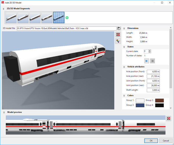
The window consists of the following sections:
- Section 2D/3D model segments: You can create a 2D/3D model from segments.
- Large Preview window: Displays the selected 2D/3D model.
- Attributes Dimensions, States, Vehicle attributes, Colors, Orientation & Position: You can adjust the values.
- Section Model preview:
 symbol: Show the complete 2D/3D model created from segments. Rotating the scroll wheel changes the display:
- Rotate down: enlarge (zoom in)
- Rotate up: reduce (zoom out)
If at the top, the 2D/3D model segments section has been expanded using the  symbol, the model is displayed in the narrow preview at the top. You can add further models to it. This allows you to create a model from segments, e.g. a train that consists of models for a power car and several railway cars. In the 2D/3D model segments section, you can change the sequence of individual 2D/3D model segments and delete 2D/3D model segments:
| Element |
Description |
|
|
Opens or closes the 2D/3D model segments section
|

|
Opens the Open window. You can select the file of a 2D/3D model and add it as a model segment behind the last model listed in the 2D/3D model segments section.
All model segments are displayed in the 2D/3D model segments list.
To show all model segments that belong to a 2D/3D model, In the 2D/3D model list, select the 2D/3D model. Then, on the list toolbar, in the Relations list box, click 2D/3D model segments (Assigning model segments to 2D/3D models).
|

|
Move segment: Click the image of the model segment, hold down the mouse button and drag the image to the desired position in the sequence of the model segments.
|

|
Delete segment: Point the mouse pointer to the bottom right corner and click the  symbol. symbol.
|
Below it, a large Preview window shows the selected 2D/3D model. If the 2D/3D model includes elements that move or change, e.g. doors or indicators, an animation is displayed in the Preview window.
5. Make the desired settings for the attributes.
The window also provides the following commands:
| Element |
Description |
|
3D model file
|
Path and file name of the selected 2D/3D model file |
|
Large Preview window
|
3D display of the selected 3D model.
-
Zoom: Turn the mouse wheel.
-
Rotate the model: Left-click and keep the mouse button pressed while moving the mouse pointer in the desired direction.
|

|
Opens the Open window for selection of a 2D/3D model file |
|
|
Resets the Preview to default settings. Does not reset the attribute values. |

|
Adjust visualization: Show options that allow you to display additional elements in the preview. For example, Show axles, Show joint and shaft length or Show ground plate:
 If the option is selected, the element selected is displayed in the preview. For example, in the case of Show ground plate, a gray, transparent ground plate is displayed below the 3D model. This view supports the orientation during rotation and tilting of the 3D model in the preview. If the option is selected, the element selected is displayed in the preview. For example, in the case of Show ground plate, a gray, transparent ground plate is displayed below the 3D model. This view supports the orientation during rotation and tilting of the 3D model in the preview.
 If this option is not selected, the element selected will not be displayed in the preview. This view corresponds to the view provided by the Network editor. If this option is not selected, the element selected will not be displayed in the preview. This view corresponds to the view provided by the Network editor.
|

|
If various model states are available, for example for moving pedestrians or cyclists, all states are displayed automatically one after the other.
|

|
Stops the animation of the states.
|
|
Vehicle attributes
|
The default values of vehicle attributes depend on the model.
|
|
Colors
|
Colors for the different areas of the model. These are based on the colors selected for the vehicle type (Editing static data of a vehicle type):
- Group 1: Color 1
- Group 2: Color 2
- Group 3: Color 3
- Group 4: Color 4
|
|
Orientation & position
|
- Scale: Factor used to scale the 2D/3D model.
- Yaw angle: Angle of rotation around z axis
- Offset X: X coordinate of the position in the network
- Offset Y: Y coordinate of the position in the network
- Offset Z: Base height of 3D model above the level surface
- Generate automatically: Position the 2D/3D model automatically
|
6. Confirm with OK.
The model is saved. If you have grouped the elements, the vehicle length is calculated as the sum of elements and displayed in the corresponding window of each vehicle type (Using vehicle types).
- In 2D mode, the vehicle is always displayed with the data from the 2D/3D Model Segments list (Attributes of 2D/3D model segments).
- In 3D mode, the 3D model of the selected file is used. Changes to the data in the 2D/3D Model Segments list result in the geometric data such as length or the axis positions of the preselected 3D model file in the simulation being ignored. This may result in that in the 3D visualization, vehicles overlap or seemingly hold very large distances. If the geometric data are not suitable for the model file when loading the network file *.inpx, a warning appears.
- Selection of a new 3D model overwrites all geometric data.
- If there is no reference between the 2D model and 3D model for a vehicle or pedestrian type, vehicles and pedestrians of that type are displayed in 3D mode as a colored cuboid.
- Since 3D elements have a static length, a length distribution can be defined in which you select various models with different lengths for a distribution.
- The color of a distribution, a class or a PT line is used to assign a color to the selected surfaces of the 3D model. Surfaces of Vissim which are to be displayed by color can be defined in the add-on V3DM module if the corresponding base models are available.
- During the simulation, the tractrix curves of the vehicles are used for vehicle display. Therefore, the turning behavior, in particular of the multi-part vehicles, seems more realistic; the higher simulation resolution is selected.
- 2D/3D model distributions are predefined for each vehicle type. The distribution for cars contains 7 different car models with different percentages (24 %, 16 %, 16 %, 16 %, 14 %, 20 %, 10 %). These vehicle models have been assigned as an elements relation of the 2D/3D model distribution Car. The other 2D/3D model distributions are also assigned as an elements relation.
- Changes to the model file of a standard vehicle model only affect the simulation result when the Select 3D Model window is closed with OK.
Defining 2D/3D models without a 3D model file
1. Select from the menu Base Data > 2D/3D Models.
The 2D/3D Models coupled list opens.
The attribute and attribute values of this network object type are shown in the list on the left, which consists of two coupled lists.
2. Right-click the row header.
3. From the context menu, choose Add Without File.
A new row with default data is inserted.
4. Into the list, enter the desired attribute values.
In the list on the right, you can show 2D/3D model segments, assign them to a 2D/3D model, and edit attributes (Assigning model segments to 2D/3D models).
