A rerouting event allows you to create a rerouting behavior on the network.
For example, to redirect a certain amount of the traffic, which would normally go through a standard main path, to other paths.
The only condition is that the starting and ending links, both of the main path and the alternative ones, must be the same.
To set a rerouting event, click on REROUTING accordion pane.
You can set several attributes, grouped in the listed accordion panes:
- Event Source
- Validity
- Publication Validity
- Description
- Location
You can open any section and set the related attributes in any sequence.
When you have set the necessary attributes, click Save to confirm.
Important: It is mandatory to set some attributes. If the mandatory attributes are not set, they are indicated in RED and marked with a warning sign. In this condition, the configuration of the event cannot be saved.
Set the events source.
|
Option |
Description |
|---|---|
|
Source |
Select the desired event source from the set of values listed in the combo-box. By default, OPTIMA is selected. |
|
Internal source |
Select an internal source from the list, for internal use only. You can also add a new source by typing a name; click Enter and OK to confirm the new internal source. Important: You cannot remove an internal source that has just been added. |
|
Source internal notes |
Add notes to the internal source if necessary. Tip: These notes are related to the edited event only, not to the source itself. |
Enter the time period of validity of the event.
|
Option |
Description |
|---|---|
|
Active |
By default, the event is set to active. An inactive event has no effect on the forecast engine, the shortest path search. etc. |
|
Start date / Start time |
By default, start date and start time are set to the current system time. The time provider system is set during the configuration phase. |
|
End date / End time |
By default, these fields are empty; this means that the event does not end. |
|
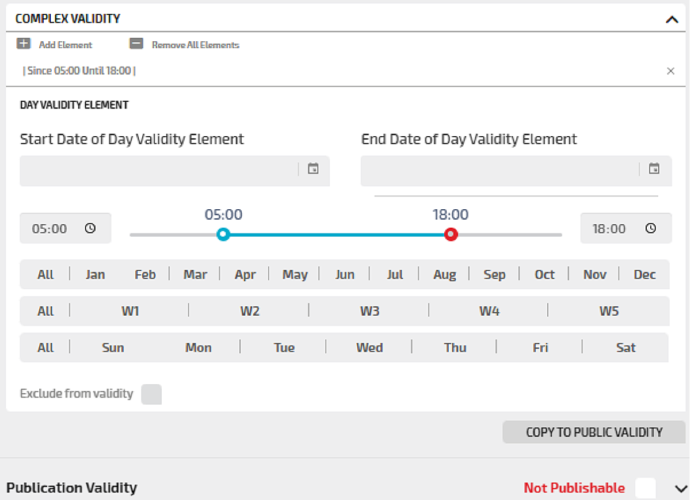
Complex validity |
Expand this section to provide more detailed validity information. You can set different partitions in the validity time period → Setting the validity time period for an event. |
|
Copy to Public Validity |
Click COPY TO PUBLIC VALIDITY to export the complex validity partitions settings to the Publication Validity section. Caution: Existing data might be overwritten. |
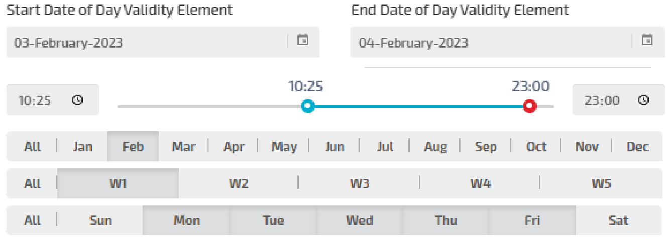
If you want to add a complex validity, you can drag the slider for setting the time interval. In the example, you can see a time interval starting from 5:00 to 18:00:
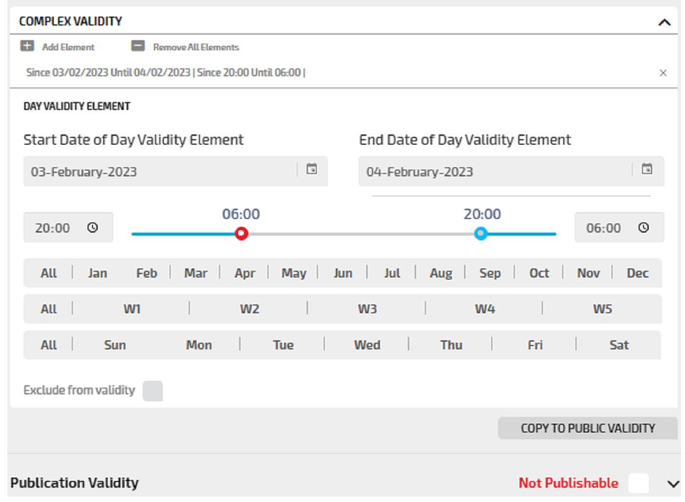
If you want to add a complex validity extending past midnight, you can drag the red dot of the slider before the blue dot. In the example, you can see a time interval starting from 20:00 of the current day to 06:00 of the next day:
The buttons All can be used to select:
-
All days
-
All weeks
-
All months
Example
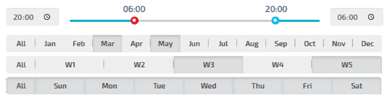
The selected validity is set from 8 PM of the current day to 6 AM of the following day.
The validity covers all days of the week, being limited to the third and fifth week of the months March and May.
An event can be published by setting some parameters.
Through these parameters you can decide whether and when an active event should be published and broadcast to the users.
|
Option |
Description |
|---|---|
|
Publishable |
By default, the event is not published. An event can be published on Virtual Message Signs (VMS) panels. |
|
Start date / Start time |
By default, start date and start time are set to the current system time. The time provider system is set during the configuration phase. |
|
End date / End time |
By default, these fields are empty; this means that the event does not end. |
|
Complex validity |
Expand this section to provide more detailed validity information for publishing the event. You can set different partitions in the validity time period → Setting the validity time period for an event. |
|
Copy to Validity |
Click COPY TO VALIDITY to copy all validity publications partitions set to the section Complex Validity. Caution: Existing data might be overwritten. |
The event can be described setting several attributes.
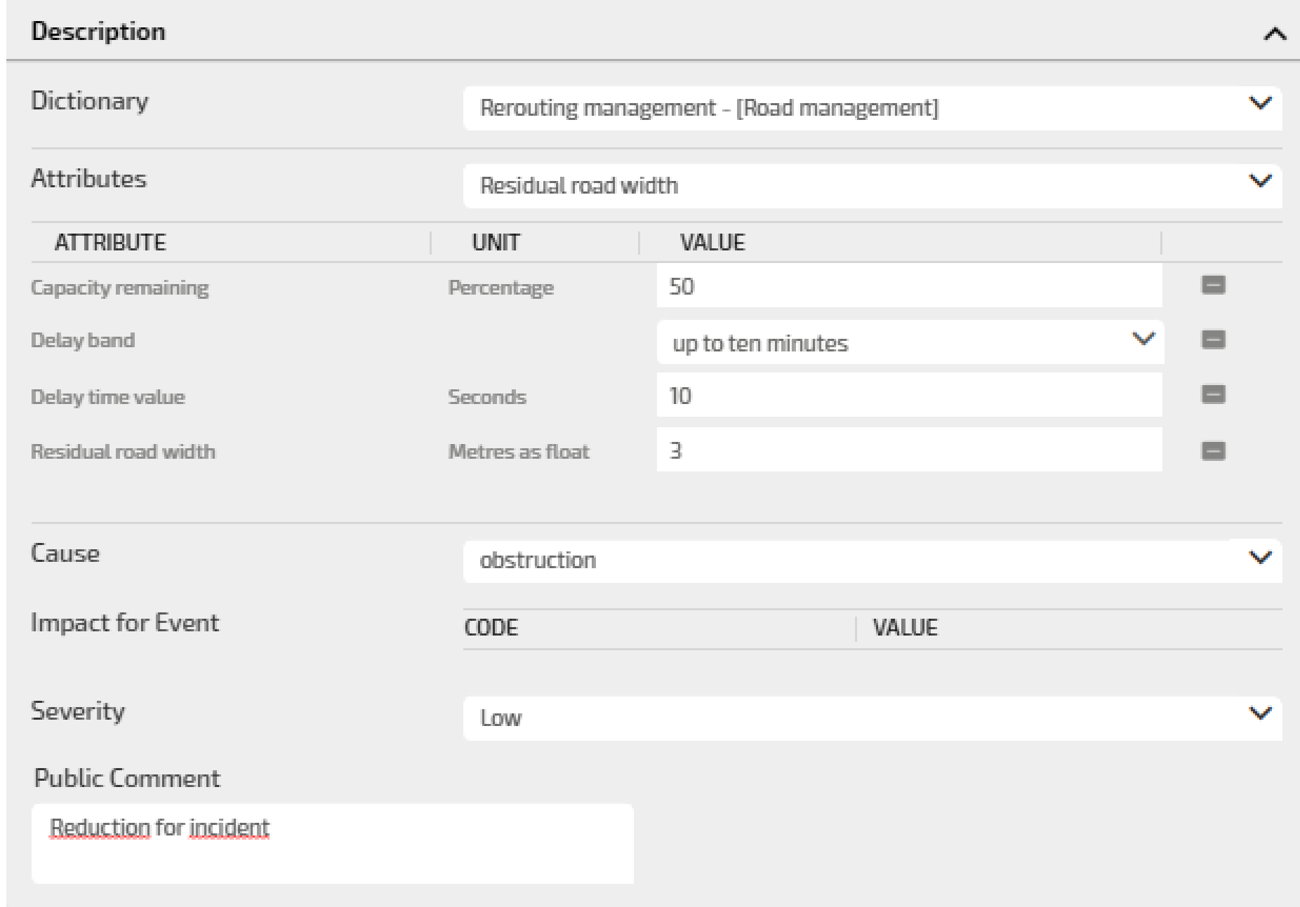
In the image an example of four attributes, listed in the order of selection.
|
Option |
Description |
|---|---|
|
Dictionary |
Select the dictionary. Every dictionary is associated with a set of attributes that can be selected and set. An attribute is linked to a specific DATEX II class. |
|
Attributes |
Select the attribute. The selected attribute is listed in the order of selection, from first to last. Every attribute is defined by three values:
|
|
Cause |
Select the cause of the event. |
|
Impact of Event |
All set attributes contribute to compute the impact of the event on the affected streets, and setting parameters such as:
|
|
Severity |
You can select one of the available values. The selected value is cast to a numerical value (range 0 - 1) that affects the priority level for that event. |
|
Public Comment |
You can add a comment to be published. |
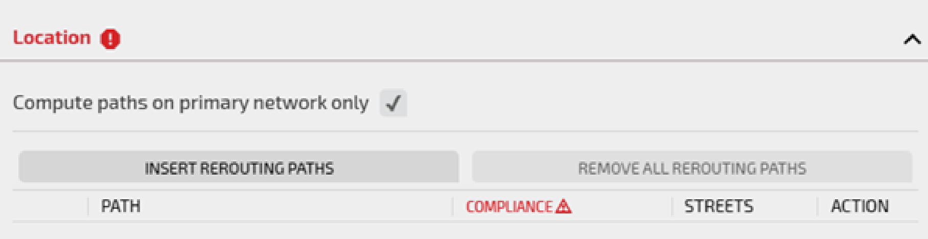
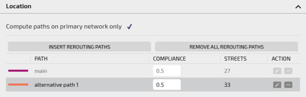
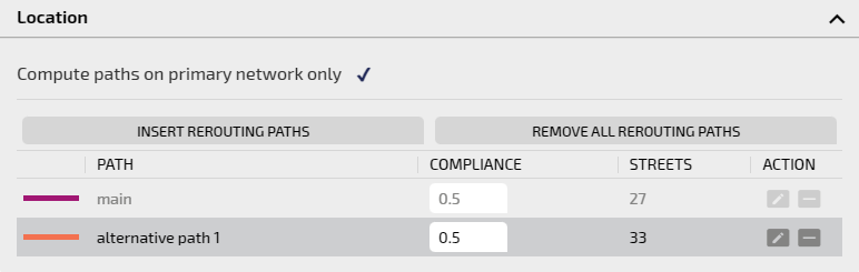
The Compute paths on primary network only is checked by default.
The "primary network" is composed ONLY:
-
By the links of the network.
-
By the streets associated with the links of the primary network (a link is made up of a sequence of streets).
If unchecked, streets not belonging to the primary network are also involved in the definition of the rerouting event.
Important: If non-primary-network streets are added to the paths of a rerouting event, the simulation engine is not able to use such event in the computation.
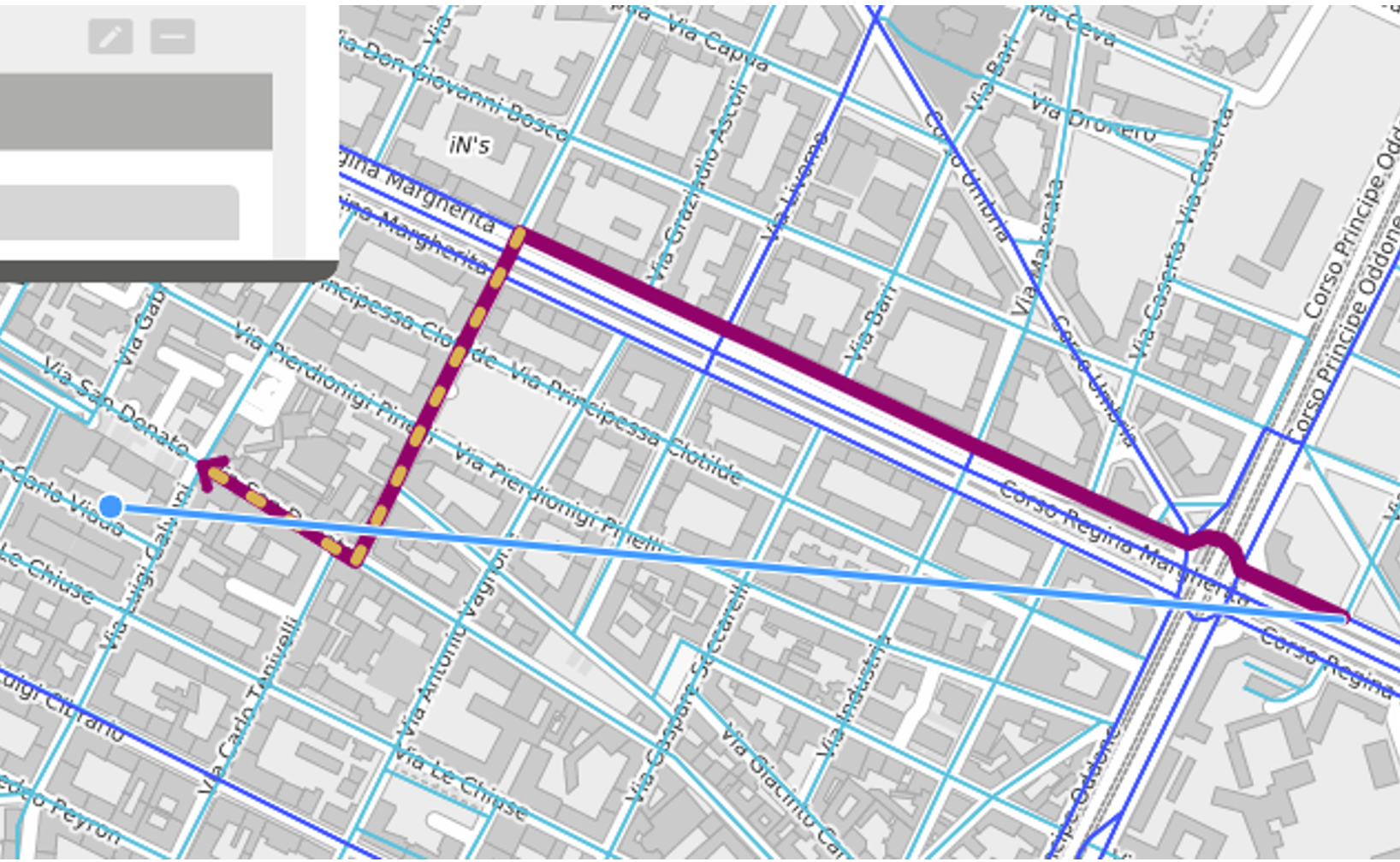
If you select a path not belonging to the primary network, this is shown with a special dashed yellow line:
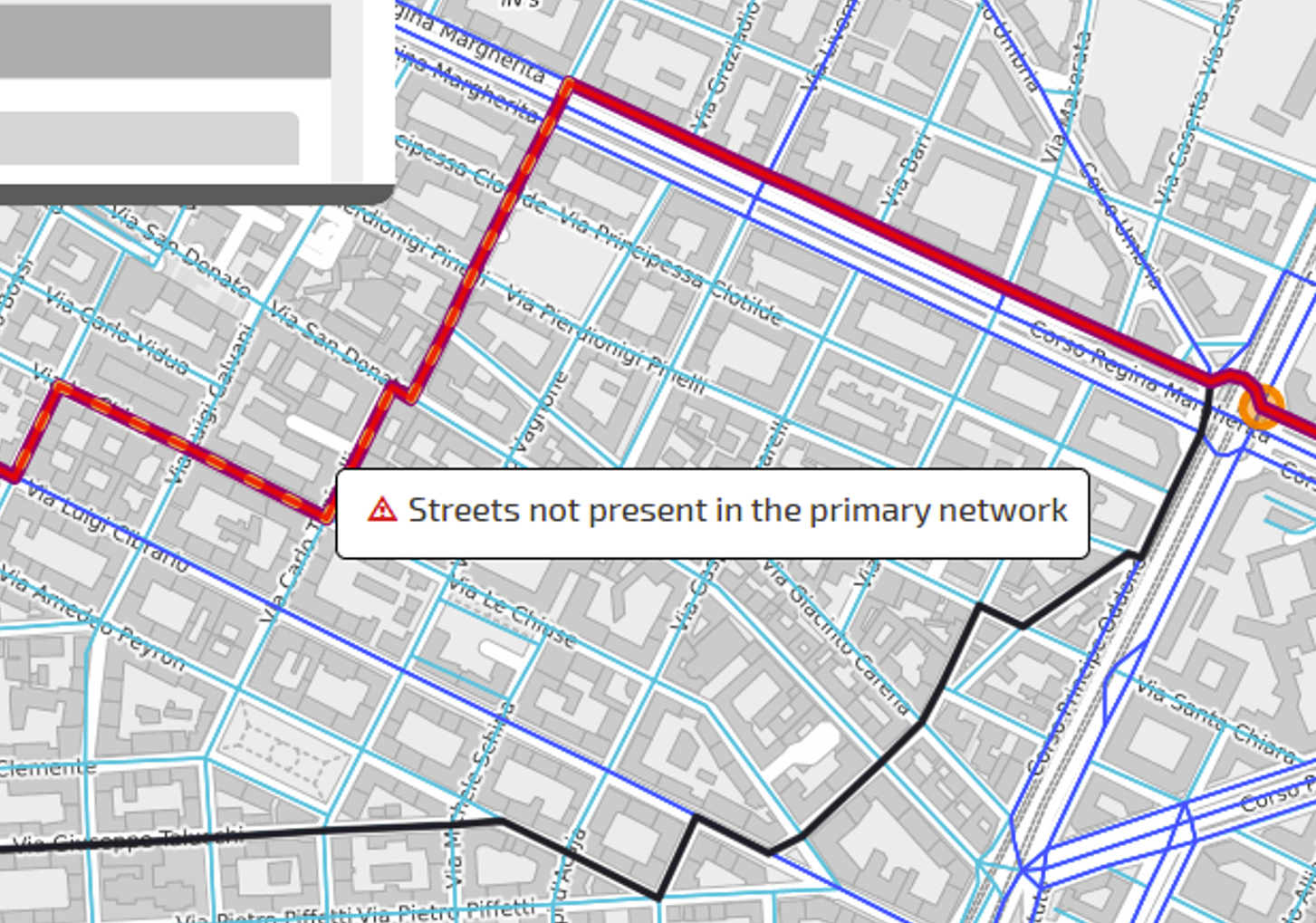
A mouse hovering interaction on the dashed yellow line shows a pop-up tag on the map explaining the different line style:
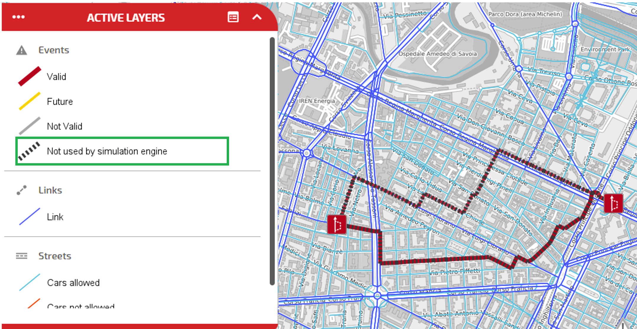
You can select and save the event. The saved event is shown with a special style (see the green box) which means that the event is not considered by the simulation engine:
You can set a rerouting defining:
- A main path.
- A list of alternative paths (routes).
For each path, a compliance must be specified to indicate the percentage of the hosted flow.
Traffic is rerouted to different paths according to specified percentage values.
-
On the map, click the event icon.
The Event window opens.
You can get the same result clicking the ADD button in the LAYER OPTIONS area.
-
Click the accordion pane REROUTING.
-
Click the Location accordion pane.
The accordion pane opens.
-
Click INSERT REROUTING PATH.
The Event window is reduced to allow you to make a selection on the map.
-
Some automatic actions are performed:
- The primary network (Links layer, dark blue) is activated.
-
The secondary network (Streets layer, light blue) is activated.

Important: The colors of the layers can be set differently.
-
The Main Nodes layer is activated.
Tip: The Main Nodes is a "virtual layer" that is not on the list of available layers. It hosts a logic contraction of some links used to model some network area such as, for example, intersections. All the links belonging to such intersection are modeled as a single “node” in order to simplify the computation of the simulation engine.
Important: The Main Nodes are highlighted during the selection of the rerouting event paths; if a link within a main node is not recognized, a rerouting path can neither start nor end entirely within a main node. In this case, the event geometry would be inconsistent and the computation as well.
-
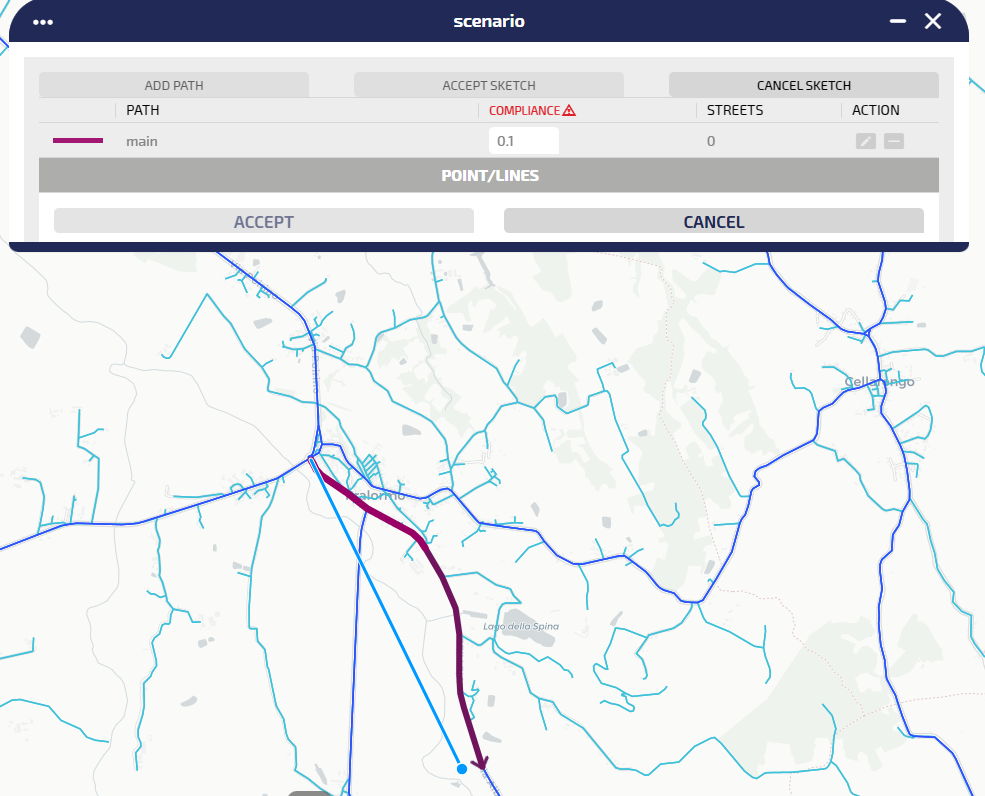
On the map, use the blue pointer to track the main path.
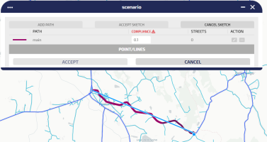
When you click on map one time, the cursor is “followed” by a purple arrow which represents the actual path:

A double left click confirms the path selection.
Tip: You can specify a list of points on the map. Left click one time to set every single point. A double left click sets the final point.

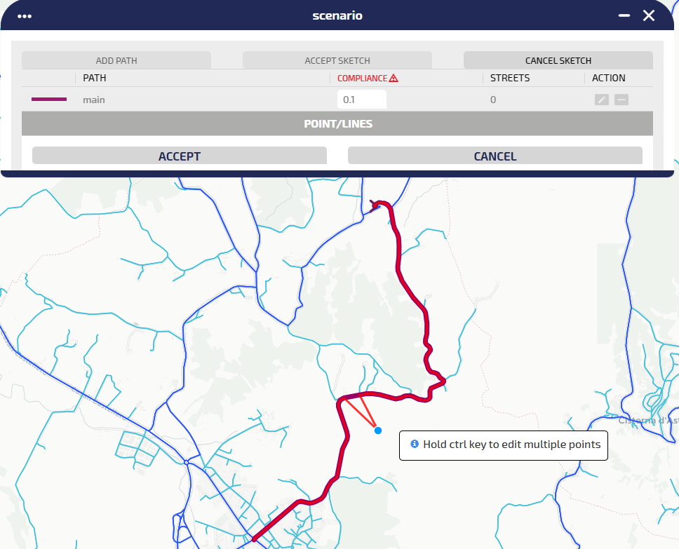
-
A red line is tracked and you can now edit the path you just created by simply clicking on the path itself and dragging the points:
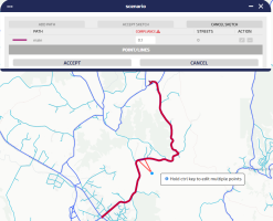
Tip: You can edit multiple points by simply holding the CTRL key. When the key is released, the path is recomputed and updated on the map.
-
Click ACCEPT to validate the tracked main path.
-
The alternative path definition is automatically activated.
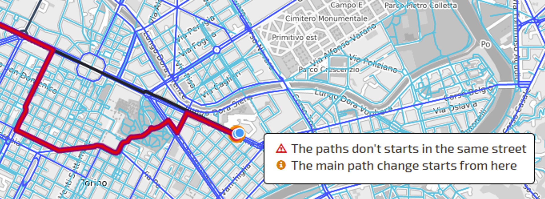
By just moving the mouse around the map window, the alternative path is automatically computed, trying to connect:
- The starting path segment of the main path (which must be the same for all the alternatives).
- The current mouse position.
- The last path segment of the main path (which must be the same for all the alternatives).
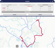
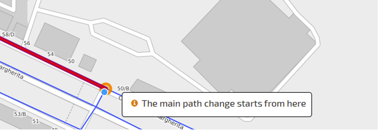
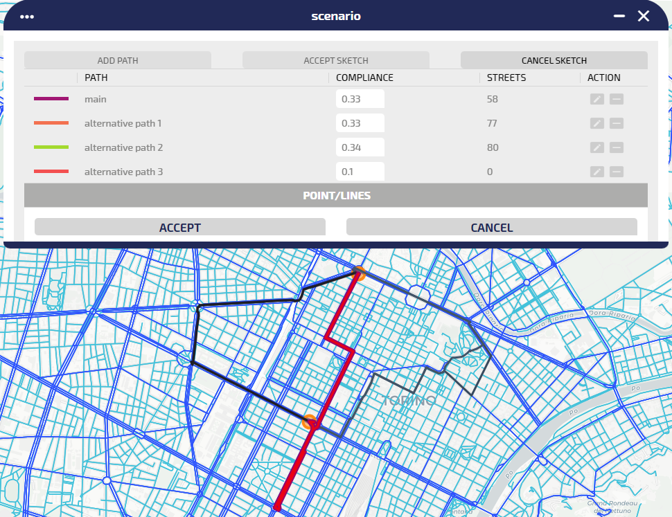
The main path is shown as a black line, while the new path “alternative path 1” is drawn in purple.
Tip: The start and the last path segment are indicated by an orange circle. A pop-up appears if the user hovers with the mouse on such circles.

-
Double click on map to confirm the map selection (as for the main path).
-
Set the compliance of the path tracked at step 10 by selecting a value in COMPLIANCE.

Tip: The compliance of a path represents the probability of the flow rerouting on that path. The compliance values are automatically adjusted as a fair split 1 / N, where N is the number of defined paths. You can change the values, considering that the sum of these N values MUST BE 1.
-
Click ACCEPT to confirm the tracked path.
If the current compliance sum is different from 1, it is automatically updated.
-
Click ADD-PATH for (N-1) times, repeating the steps from 10 to 13, to add (N-1) rerouting paths.
Tip: The rerouting paths are limited by the orange nodes.
-
The already-defined alternatives are all shown in gray scale colors. If the returned path doesn't include either the start or end segment corresponding to their position on the main path, the entire event is inconsistent.
The system shows:
- A red triangle icon closes the STREETS label
- A value of STREETS= 0 is associated with the wrong alternative path (in the example, the alternative path 2)

A mouse hover interaction shows the reason of the error:

-
Starting from the paths set that define the rerouting event, you can make two specific actions on a single selected path:
- Click on
 to update the path.
 - Click on
 to remove the path.
- Click on
-
Click ACCEPT SKETCH to accept the current configuration (without errors) and exit from map selection mode.
-
Click CANCEL SKETCH to exit from map selection mode.
Important: If the tracked path is not accepted, the entire rerouting sketch is canceled.
-
Click SAVE to enable the rerouting event you just set.
Important: The SAVE button is enabled only if the sum of the compliances of the listed paths is 1.
On the map, the new rerouting event is shown through its icon:


Tip: Considering the streets details featured, if the street belongs to the main path, you can open the SHOW RELATED LINK DETAILS (RED rectangle).
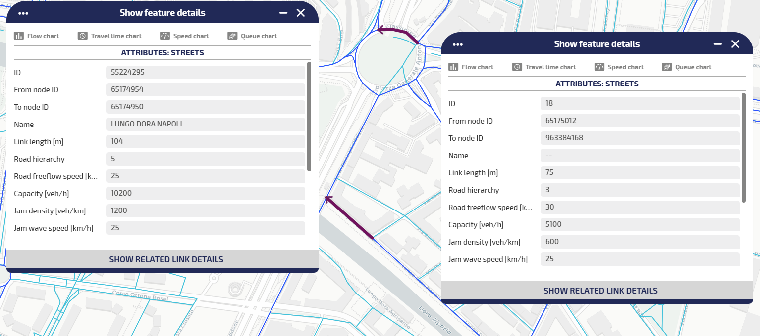
In the image on the left, as for the street detail related to street ID=55228044, it is not belonging to a main path: therefore the button SHOW RELATED LINK DETAILS is not selectable.
On the right, as for street ID=55228419, you can access details of the link.
Event operations
Several operations are available for the management of an event.
You can define:
- start date
- end date
- time period for the day (for example, from 2 AM to 5 AM)
- months of the year
- weeks of the month
- days of the week
You can also use All buttons to select:
-
All days
-
All weeks
-
All months
-
On the map, click the event icon.
The Event window opens.
-
In the section Validity, set:
- start date and time
- end date and time
The base parameters for the validity of an event are set and if you don't need a more detailed scheduling, jump to the last step.
-
Click the Complex Validity accordion pane.
The accordion pane opens.
- Click the Add Element icon to define a complex validity setting.
- Select with a mouse click all necessary items (see the figure above): start/end date, day time period, months, weeks, and days.
- Select the Exclude from validity check-box to exclude all complex validity items from validity (by default, they are included).
- Repeat steps 4, 5 and 6 to add a new complex validity set.
- Click COPY TO PUBLIC VALIDITY to export the complex validity settings to the Publication Validity section.
- Click SAVE.
All the configured complex validity set are listed under the Add Element icon.
You can remove all complex validity time period previously set for an event.
-
On the map, click the event icon.
The Event window opens.
-
Click the Complex Validity accordion pane.
The accordion pane opens.
- Click the Remove All Elements icon to delete all items listed under the Add Element icon.
- Click SAVE.
All complex validity settings are deleted.
You can unpublish an event.
Tip: An unpublished event can be both active or inactive.
-
On the map, click the event icon.
The Event window opens.
-
In the section Publication Validity, deselect the Publishable check-box.
The check-box label turns to Not Publishable and is colored in red.
-
Click SAVE.
An unpublished event is not displayed on Virtual Message Signs (VMS) panels, but is represented on the map.
In the bottom Buttons Bar you can select different operations.
Every operation acts on the whole set of attributes previously set in the GUI.
You can delete an event displayed on the map that hosts an active instance of the layer Events.
-
On the map, click the event icon.
The Event window opens.
-
Click DELETE.
A pop-up window opens.
- Click OK to confirm the deletion.
The icon of the event is deleted from the map.
You can save a template based on an event configuration. A template represents a repeatable "model" for the definition of similar events. Saved templates can be loaded to speed up the configuration of a new event.
-
On the map, click the event icon.
The Event window opens.
-
Open one or more sections and set the attributes of the event.
A pop-up window opens
-
Click TEMPLATE > Save as template to save the current attributes as a template that can be retrieved and updated.
Important: You can save different templates with the same name (templates are associated with different internal identifiers), but this is not considered a best practice.
You can load a saved template.
-
On the map, click the event icon.
The Event window opens.
-
Click TEMPLATE > Load template to load a stored template.
You can select one template from the list of available templates.
-
Click the Load icon to load it in the related template.
The Event Situation GUI is set with the attributes of the loaded template.
The preview of an event provides a short description of the event.
-
On the map, click the event icon.
The Event window opens.
-
ClickPREVIEW.
A pop-up window opens and displays some base information associated with the event.
You can determine the end of an event.
-
On the map, click the event icon.
The Event window opens.
-
Click END.
The event icon is grayed.
You can update only the update time associated with the event. The update time can be used by external agents for their purposes.
-
On the map, click the event icon.
The Event window opens.
-
Click UPDATE.
A pop-up window opens and confirms the success of the operation.
Tip: When you save an event, you update ALL the information associated with the event.
You can update an event displayed on the map that hosts an active instance of the layer Events.
-
On the map, click the event icon.
The Event window opens.
-
Open one or more sections and set the attributes of the event.
- Click SAVE to confirm all settings.
All data set in the Event window are saved.
Tip: Some attributes are mandatory. If the mandatory attributes are not set, they are indicated in RED and marked with a warning sign. In this case, the configuration of the event can not be saved.