In the Junction editor, you can define signal controls. A signal control describes the totality of the signal control data at one node or at one main node.
For Optima, there are two possible ways of modeling the timing of signals:
- Signal-group-based signal control for fixed signal timing over the complete simulation
- External controls for modeling dynamic signal timing
Here we provide the steps in a nutshell. For details on signal control modeling, please refer to the Visum user manual.
The signal control contains a set of signal groups that describe lane-based signal controls and turn-based signal controls in detail. For each signal group, you can set a Green time start attribute and a Green time end attribute. These times cannot vary during the day.
By editing signal timing, you can set the cycle time and the green times. The relation between the signal controls and the network is established by allocating the signal groups to each lane turn. Each lane turn can be allocated to any set of signal groups created for a signal control.
Step 1: Creating a signal-group-based signal control
-
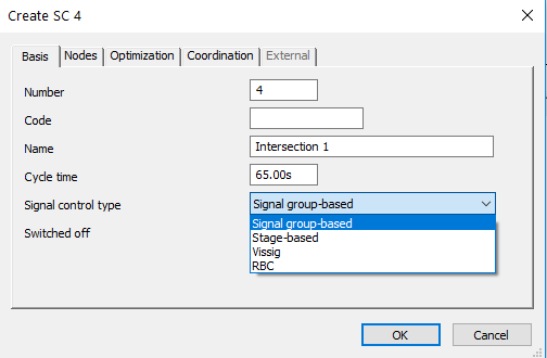
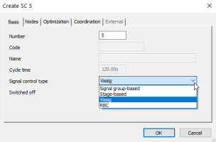
In the Junction editor, click the Create SC icon.
The Create SC window opens. The signal control is automatically allocated to the present node or to the present main node.
-
From the Signal control type list, choose Signal group-based.

-
Enter a Name and set the Cycle time.
Step 2: Creating signal groups
-
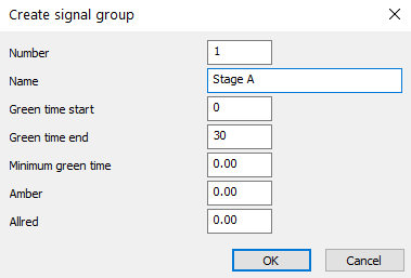
In the Junction editor, click the Create a signal group icon.
The Create signal group window opens.
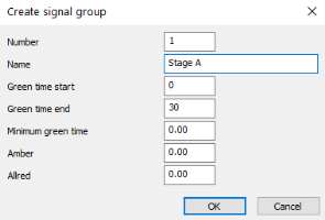
- Edit the key attributes Green time start and Green time end.
-
Repeat steps 1 and 2 to create one signal group for each stage.
Step 3: Editing signal times
In the Signal Timing view of the Junction editor, you can edit signal times that have already been set up. You can change the cycle time and the offset.
The next image shows the definition of signal group timing:
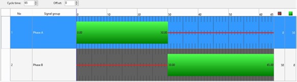
Each row represents one signal group. The thick green bars indicate the green times. The thin red bars indicate the red times.
Step 4: Editing the allocation of signal groups
Finally, you need to edit the allocation of selected signal groups to make them work properly.
Once you have created signal groups, you can now edit a new field in Geometry view for each lane: the field Signal group. You can choose from the signal groups that have been created in order to assign a signal group to each maneuver, thus assigning the green times and the red times defined before.
The next image shows the definition of the relationship between lane turns and signal groups:
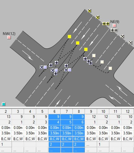
Vissig is an external interface for Visum. Vissig allows you to manage complex signal control data. In the process, existing signal control data can be converted into new external controllers. The external signal control data is saved to a *.sig file.
The Vissig interface lets you model signal timings. You can:
- Edit green times graphically
- Display and graphically edit the stage allocations of signal groups
- Allocate different signal programs to different time intervals at identical nodes in a time-varying manner
- Manage complex signal controls located in the Visum network
- Edit signal control data for later export to Vissim
In the table, the list of the sequences of signals that you can manage in Vissig and supported by Optima:
|
Sequence |
Code |
Supported |
Red status CLOSED |
Green status |
|---|---|---|---|---|
|
Red |
1 |
YES |
Not applicable |
Not applicable |
|
Green |
2 |
YES |
Not applicable |
Not applicable |
|
Red-Red/Amber-Green-Amber |
3 |
YES |
Red |
Green |
|
Red-Green |
4 |
YES |
Red |
Green |
|
Red-Red/Amber-Green-Flashing Green-Amber |
5 |
YES |
Red |
Green |
|
Red-Green-Flashing Green |
6 |
YES |
Red |
Green |
|
Red-Green-Amber |
7 | YES |
Red |
Green |
|
Off |
9 |
YES |
Not applicable |
Not applicable |
|
Red-Off |
10 |
YES |
Red |
Off |
|
Red-Off-Amber |
11 |
YES |
Red |
Off |
|
Off-Green |
12 |
YES |
Off |
Green |
|
Flashing Amber - Off |
|
NO |
Not applicable |
Not applicable |
|
Red-Green-Flashing Red |
14 |
YES |
Red |
Green |
|
Flashing Red-Off |
15 |
YES |
Flashin Red |
Off |
|
Red-Green-Flashing Green-Amber |
20 |
YES |
Red |
Green |


Step 1: Creating an external signal control
-
In the Junction editor, click the Create SC icon.
The Create SC window opens.
-
In the Signal control type list, click Vissig. Other than when creating a signal-group-based signal control, you cannot edit any other parameters.

Step 2: Creating signal groups
-
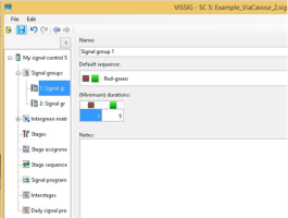
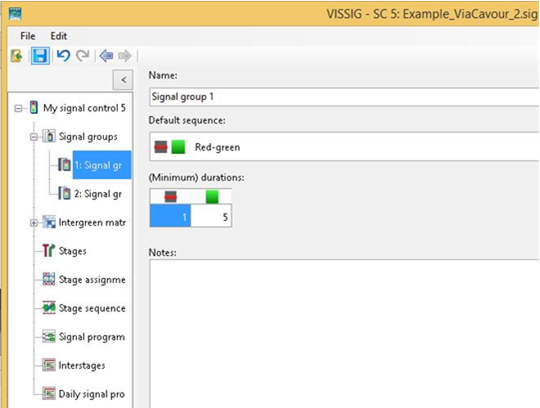
In the Junction editor, click Edit Vissig controller.
The Vissig window opens.
-
Create as many signal groups as the signal-control has stages. In the next image, for example, there are two stages and thus two signal groups.
You can choose from five predefined default signal sequences.
Step 3: Adding signal programs
On the Signal program tab, you can add as many signal programs as you need to define.
In the following example, two signal programs have been created.
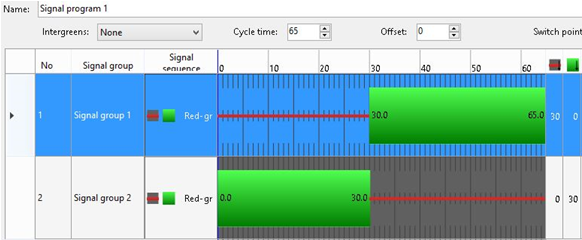
Signal program 1 looks like this (cycle time = 65):
Signal program 2 looks like this (cycle time = 90):
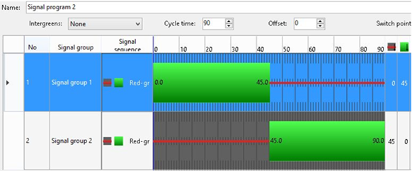
You can stretch or compress the green bars to edit the green times.
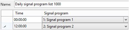
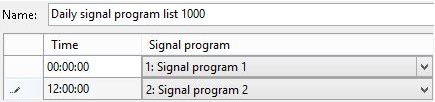
Step 4: Adding daily signal programs
- In the Navigator, select Daily signal program list.
- Add as many daily signal programs as you have day types in your model.
-
For each daily signal program, add the hourly brackets you need. The Time field indicates the starting time of each bracket.
The following example shows the creation of a daily signal program with two brackets of 12 hours each.
- Associate a daily signal program to a valid day by inserting into the field notes the code DVAL = , followed by the ID of the valid day. Thus you can define different signal plans for each modeled day type.
You can convert a Vissig controller to the internal Visum format by clicking the  Convert SC to Visum controller icon on the toolbar.
Important: Conversion, however, results in the loss of all additional information that is not included in the Visum data model.
The folder containing the *.sig files must be the same as the one that has been specified under File > Project directories > Edit project directories.
Important: If the folders are different, Visum will not recognize the *.sig file as associated to a junction in the Junction editor.