When using ANM import most of the nodes are fine in terms of extent (to reduce the effort for adjustments, see chapter the Tutorial_ANM_BestPracticeGuide).
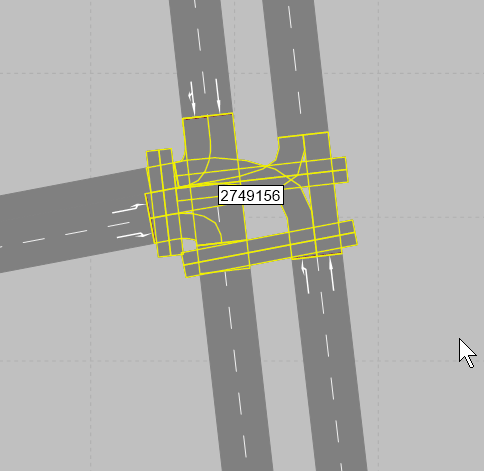
In the figure you can see a correctly modeled segment node encompassing the stop lines and all turns.
When using ANM import, large complex nodes or main nodes typically require corrections of the geometry representing pocket lanes, lane turns, crosswalks etc. This typically means shifting links and connector links in PTV Vissim and as a result edges and movements may become non-unique.
A simple example of adjustments actions can be analyzed in the next figure (from left to right):
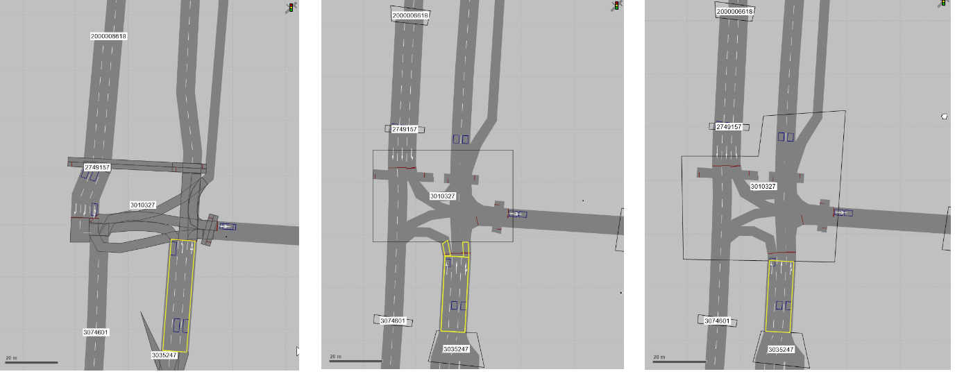
- Left: the yellow highlighted edge has a unique sequence of PTV Vissim links and connector from node 3035247 to node 3010327.
- Middle: the geometry of the PTV Vissim links is changed and the node 3010327 is changed to a polygon node. As a result, the yellow highlighted edge does not have a unique sequence of PTV Vissim links and connector links.
- Right: the polygon node is adjusted so that it includes the connector links at the northern end. As a result, the yellow highlighted edge has a unique sequence of PTV Vissim links and connector links again.
A set of specific examples can be useful to highlight some very common situations.
The figure shows a complex example and common pitfalls related to the adjustments.
Important: You must check the PTV Visum model in parallel to have the same geometry as in PTV Vissim (node numbers are the same in PTV Visum and in PTV Vissim).
When using ANM import the adjustments are most conveniently done by converting the segment nodes to polygon nodes. This makes polygons large and therefore they can:
-
Include wrong PTV Vissim links.
Tip: Please check that the Node–Link geometry is correct.
-
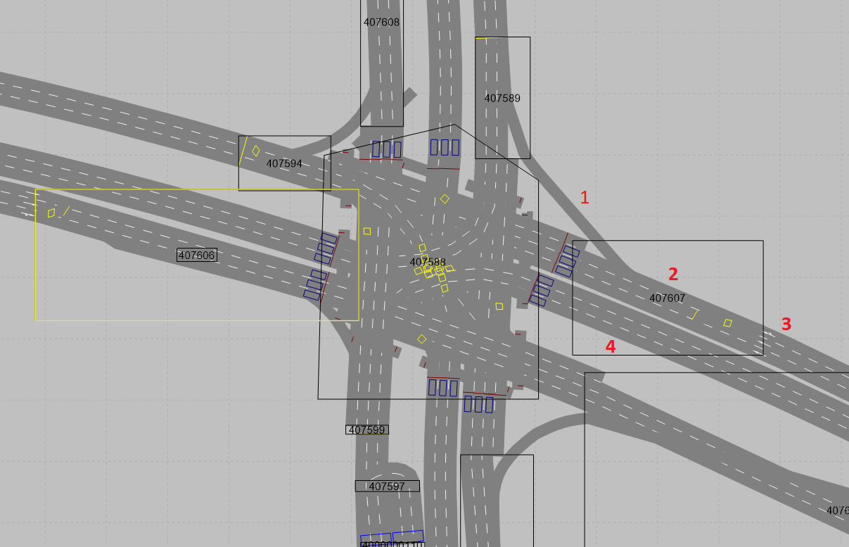
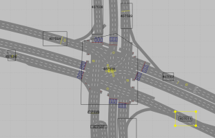
In the figure, every node in PTV Visum has some links flowing into it and some links flowing out.
For the node 407607 these are the links (marked with 1-3), which should be contained by the polygon area in PTV Vissim. No other links (marked as 4) should be contained in the polygon.
-
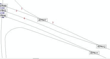
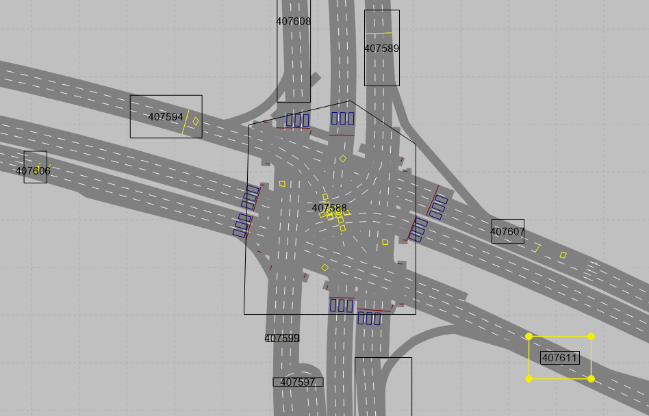
In PTV Vissim the converted polygon node of the first figure includes the wrong link 4 and this must be adjusted as in the figure:
-
-
Produce overlapping nodes 407606 and 407598
- This must be adjusted as in the previous figure, where you can see the node polygons after reposition and reduction.

In PTV Visum ramps or bypass can be modelled outside of the node as shown in the figure.
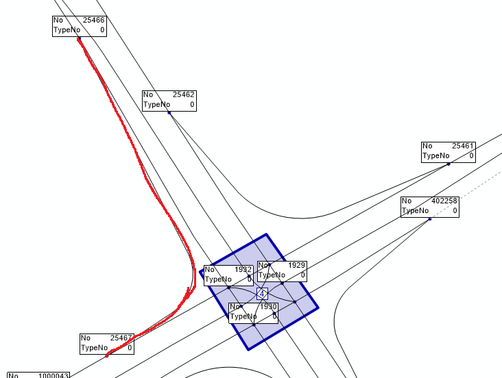
In this case the ramp or bypass is modelled as a PTV Visum link from node 25466 to node 25467.
In PTV Vissim this ramp passes through the (main) node 1929 and therefore does not represent the same node sequence as in PTV Visum.
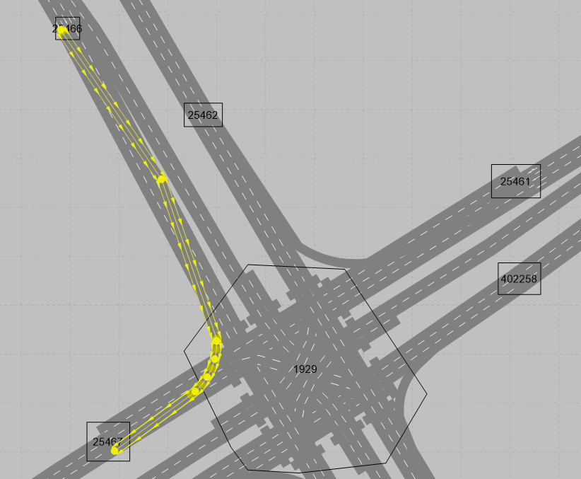
The final figure shows the correct geometry of this ramp (ramp is not contained in any other nodes than the correct nodes 25466 and 25467).
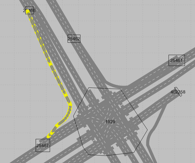
In this figure is topologically removed the ramp from the main node 1929.
In case of multilevel intersections, each level (layer) of the intersection should be modeled separately, as a part of corridor to which it belongs.
The assignment of the proper links to the node can be adjusted in Vissim using the edges list of the specific node.
- Ensure that the relevant node is a segment node and not a polygon node.
-
Select Lists > Network > Edges.
The list Edges opens.
- Ensure that a node-edge graph has been generated
- In the Edges list, the edges of the segments nodes are displayed in the Vissim network.
- Right-click one entry of the list.
- From the contextual menu, choose Delete node segments.
- All segments of the turn edge are deleted from the Edges list and from the network editor.
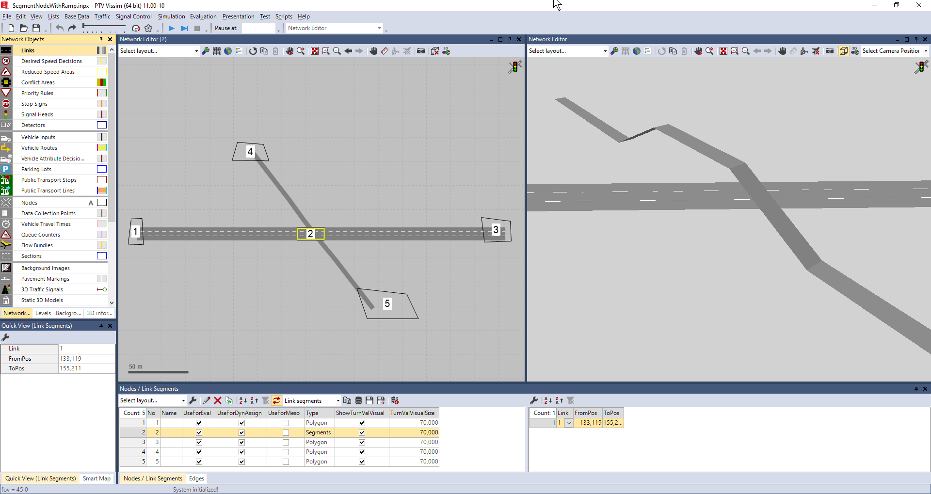
The figure shows a network with the valid edges 1-2, 2-3 and 4-5 (whit a jump over node 2). The Vissim links along edge 4-5 are additionally modeled with zOffsets for visualization purposes (visible in the right side of the figure).
Sometimes cordon zones connecting to multiple nodes and zones connecting to nodes with multiple links are unavoidable.
This requires a manual refinement.
The figure provide an example of the necessary working steps, highlighting the pitfalls and how these are fixed.
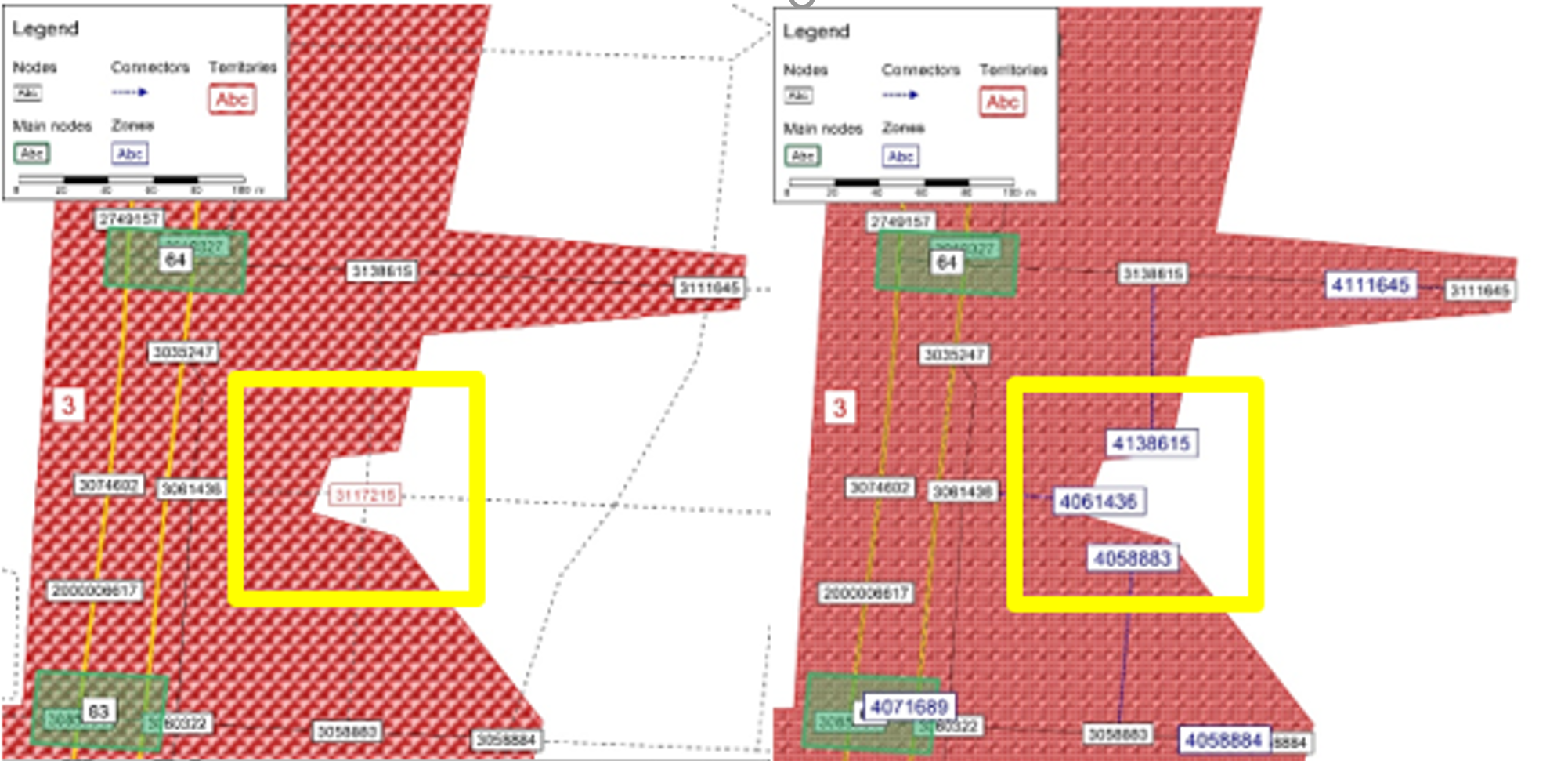
The red area (left side) shows a selection of a subnetwork in PTV Visum.
The yellow rectangle surrounds node 3117215 (red) which intentionally shall not be included in the subnetwork.
In the right side, the resulting subnetwork does not include node 3117215, but are present the cordon zones 4138615, 4061436, and 4058883. Each of these zones is connected to nodes with multiple links.
In the next figure (left) you can see the network in PTV Vissim directly after the ANM import.
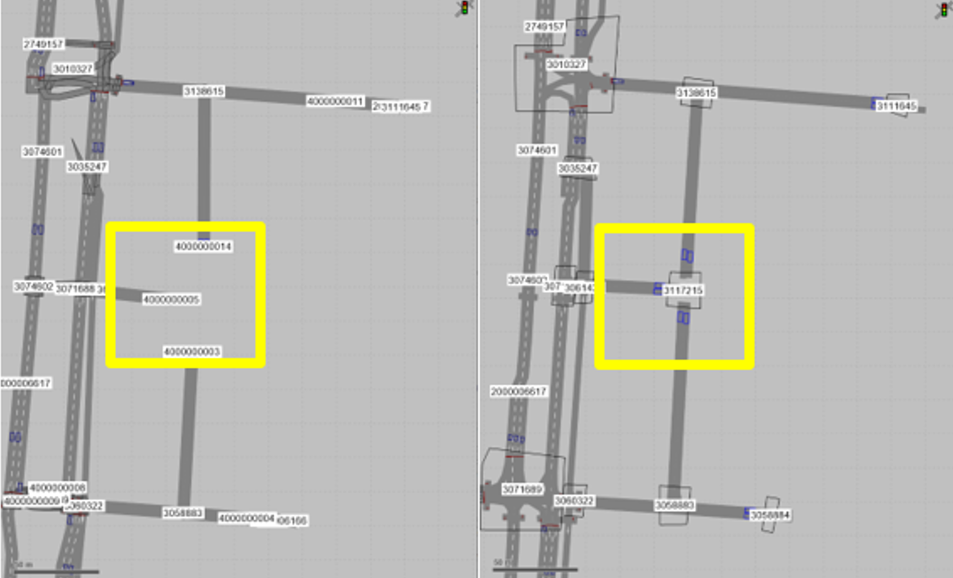
The zone connectors are converted to links in PTV Vissim.
PTV Vissim nodes 4000000014, 4000000005 and 4000000003 have been added. These artificial nodes do not exist in the PTV Visum model. Therefore, no data that PTV Optima forwards to PTV Optima Micro can be mapped to these nodes and the related edges in PTV Vissim.
In the right side artificial nodes have been deleted, and the new node 3117215 has been added. The links leading to and starting from this node have been placed correctly.
Parking lots of type zone connector have been added and placed along the edges.
Important: The number attribute of the parking lot is not relevant, as are the zone and zone number. However, each edge with a zone connector parking lot that acts as an origin or destination must have a unique zone.
In the example, you need at least 3 different zones for the 3x2 (origin and destination) parking lots on the 3 edges leading to and from node 3117215.
There is no geometry associated to the node 3117215. The edges leading to and from this node are not connected to each other and serve as inflows and outflows.
If you want to set a geometry inside this node, then it should have been added to the selection of the subnetwork at the beginning of the process.
Other nodes and geometries have been fixed as well.
In case of border nodes containing parking lots representing demand, the specific walkaround should take place in Vissim.
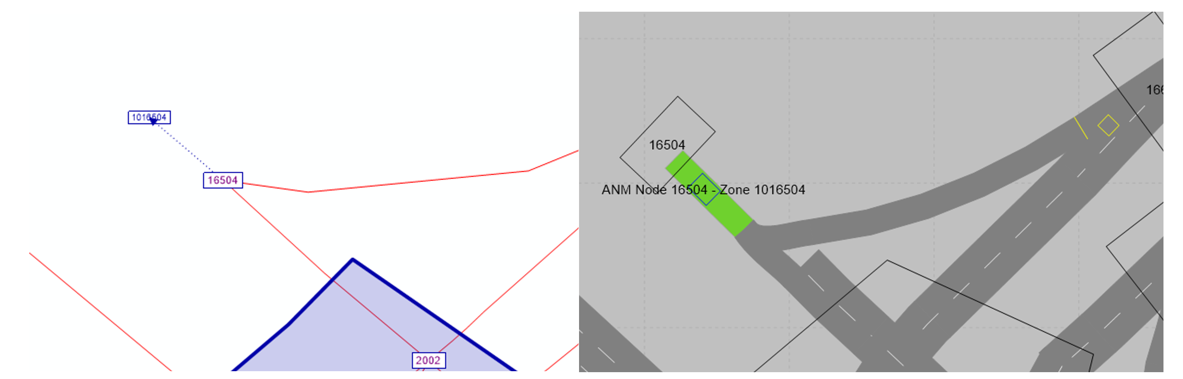
As presented in the figure (Visum on the left, Vissim on the right) a short artificial link (dummy link) should be added in Vissim (the green one). A parking lot for a specific zone 1016504 should be placed on this link. At the end of the link a proper node (the one to which a connector is attached in Visum) should be placed (node 16504).
Important: This workaround avoids additional long edges in the subnetwork, minimizing the network size and the computation time. However, events placed by Optima Micro along Vissim links, which are shared by different Vissim edges, are not be represented correctly. This must be avoided for edges and nodes without parking lots.
Tip: If the connector of zone 1016504 in the Visum subnetwork is representing a real link in the main Visum model, then it is better to include this link and its additional node in the subnetwork generation (which might however require to add a long additional edge).
A demand connector is a connector which exist in the base macro model (it’s not the cordon zone created automatically due to the subnetwork cutting).
Traffic is entering and leaving the primary network via demand connectors. Due to the requirements of Optima Micro and the architecture of the Macro model, a connector should be attached to an additional “dummy” link in the Macro model (a very short link preventing connecting zone directly into primary network to a node with more than one link).
The concept of the demand connector is shown in the figure:
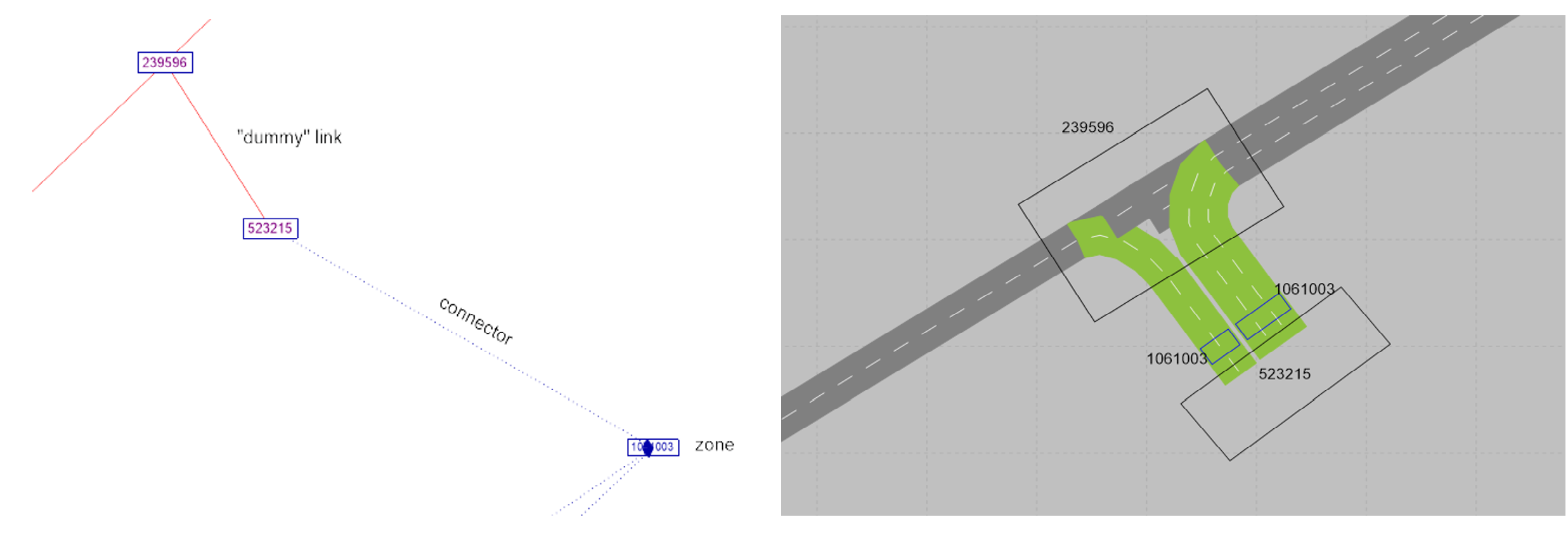
The same concept should be kept in the Optima Micro model.
Vissim links or link connectors (green elements connecting links in PTV Vissim) should avail the entering and leaving of the network. Nodes number are kept the same as in the Macro model to provide consistency.