Implicit signals and node delays are modeled at the link level because the propagation at the node level is instantaneous.
TRE implements two alternative link delay models:
- Fundamental diagram distortion
- Uniform time shift of the forward wave arrival time; see figure in: → Uniform time shift of the forward wave arrival time
The choice between the two models (or none of them) is driven by the value of the parameter NodeDelayModel (→ Supply parameters).
If the parameter NodeDelayModel = 1, the original fundamental diagram of the link (dashed line in the next image) is distorted in order to increment the travel time of a quantity equal to the sum of the node delay and the implicit signal.
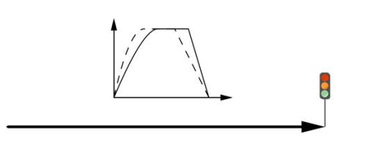
The new travel time t’ is given by:

- L is the length of the link.
- V is the link’s free flow speed.
- i is the end point constant delay.
- c is the signal cycle time in seconds.
- g is the effective green share (value in the interval [0,1]).
Recomputing v(q) as L/t’, the new fundamental diagram is shifted to the right (slower speed for the same flow value).
The advantage of this delay model is that the delay can be reasonably applied to the hypercritical states, too.
If the parameter NodeDelayModel = 2, the forward wave arrival time is shifted by a constant delay dt.


This results in a global time shift of the outflow cumulative.
The advantage of this delay model is that it makes it possible to explicitly compute the hypocritical queue, that is the number of vehicles that would have reached the head of the link under standard conditions but did not due to the additional delay.
At any given time, the number of vehicles in queue is simply given by the difference between the original cumulative sending flow and the delayed one.