The OpenLR standard focuses on creating map-independent references for line, point, and area locations.
Requirements for the maps
To solve locations properly and to generate a map-independent reference, a map should contain some particular data.
Important: If a digital map provides less information than required, the encoding and decoding processes do generally still succeed, but the error rate may increase considerably.
A map should contain:
| Map element | Description |
|---|---|
|
Coordinates in WGS84 |
Every node in the network should have coordinates in the WGS84 format. The preferable accuracy is decamicrodegrees for all values. |
|
Length in meters |
Every line should have a length value in meters indicating the line’s real dimension along the geometry. |
|
Geometry |
Every line should know about its real geometry in the real world. Lines should not be abstracted by the air line. |
|
Functional road class (FRC) |
Every line in the network should have a functional road class value indicating the line’s importance in the network. |
|
Form of way (FOW) |
Every line in the network should have a form of way value indicating the line’s physical properties. |
A location reference is a description of a designated part of a digital map or a sequence of geographical positions, based on Location Reference Points (LRPs) model.
Location points provide a logical view on the data required to describe a location uniquely.
A location reference point determines a position on a digital map. If further line or path properties are provided, a location reference point determines a line on a digital map. Besides the position or line information, additional data may be used to further specify the character of a location.
Each location reference point is a combination of several building blocks. The composition of a local reference point depends on the location type.
A coordinate pair is a pair of WGS84 longitude (lon) and latitude (lat) values, associated to a geometric point on a digital map. The (lon,lat) values should be stored in decamicrodegree resolution (five decimals). Coordinates may be expressed in absolute or relative values.
In the physical format, geo-coordinates should have a compact representation. Instead of using floats, the decimal values are converted to Integer values.
For the absolute representation, the values are generated using the following equation, that calculates a 24-bit Integer representation:
The resolution parameter is set to a value of 24, to get a maximum coordinate resolution (“error”) of about 2.4 meters. The backward translation is described as:
Relative geo-coordinates are used to describe differences between two consecutive coordinates. The difference is calculated for each value (lon,lat) separately. The current and previous values represent the latitude (longitude) value in degrees. The difference between these two values is multiplied by 100000 (105) in order to resolve an Integer value.
The FRC of a line is a road classification based on the importance of the road that is represented by the line.
The possible values of the FRC attribute cover the range of navigable roads from highest to lowest importance. If there are fewer or more FRC values defined in the encoder map or in the decoder map than the 8 values listed below, a proper mapping needs to be performed or less important classes are ignored.
| FRC | Description |
|---|---|
|
0 |
Motorways - Freeways - Major Roads. |
|
1 |
Major Roads less important than Motorways. |
|
2 |
Other Major Roads. |
|
3 |
Secondary Roads. |
|
4 |
Local Connecting Roads. |
|
5 |
Local Roads of High Importance. |
|
6 |
Local Roads. |
|
7 |
Local Roads of Minor Importance. |
The FOW describes the physical road type of a line.
Possible values of the FOW attribute are:
| FOW | Integer code | Description |
|---|---|---|
| UNDEFINED | 0 | The physical road type is unknown. |
| MOTORWAY | 1 | A motorway is defined as a road permitted for motorized vehicles only in combination with a prescribed minimum speed. A motorway has two or more physically separated carriageways and no single level-crossings. |
| MULTIPLE_CARRIAGEWAY | 2 | A multiple carriageway is defined as a road with physically separated carriageways regardless of the number of lanes. If a road is also a motorway, it should be coded as such and not as a multiple carriageway. |
| SINGLE_CARRIAGEWAY | 3 | All roads without separate carriageways are considered as roads with a single carriageway. |
| ROUNDABOUT | 4 | A roundabout is a road that forms a ring on which traveling is allowed only in one direction. |
| TRAFFICSQUARE | 5 | A traffic square is an open area that is enclosed or partly enclosed by roads. The traffic square is used for non-traffic purposes. It is not a roundabout. |
| SLIPROAD | 6 | A slip road is a road especially designed for entering or leaving a line. |
| OTHER | 7 | The physical road type is known but does not fit into one of the other categories. |
The bearing (BEAR) describes the angle between the true North and a line that is defined by the coordinate of the LRP and a coordinate BEARDIST along the line defined by the LRP properties.
The constant BEARDIST is defined as:
| Abbreviation | Description | Value | Unit |
|---|---|---|---|
| BEARDIST | Distance measured along the line between two coordinates positioned on this line | 20 | m |
If the line is shorter than BEARDIST, the opposite point of the line is used, regardless of BEARDIST.
BEAR is measured in degrees and it is always positive (measuring clockwise from the North).
If BEAR is measured from the start node, the opposite node is the end node of the line. If the bearing is measured from the end node, the opposite node is the start node of the line.
The next image illustrates how to determine the second point for the bearing calculation.
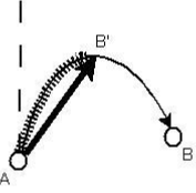
The image shows a line from A to B that is longer than BEARDIST. The shaded part of this line is exactly BEARDIST meters long so that the point marked with B’ is BEARDIST meters away from A when we walk along the line from A to B. The straight line from A to B’ is now considered for the calculation of the bearing value. Note that this is different from the angle that we would calculate if we always took the opposite node of the line (B in this case).
The DNP field describes the distance to the next LRP in the topological connection of the LRPs. The distance should be measured in meters and should be calculated along the location reference path between two subsequent LRPs. The last LRP should have a distance value of 0.
The next image shows an example of the distance calculation and assignment.
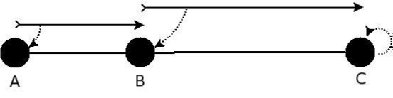
The three LRPs are in a sequence from A over B to C. Therefore, the distance between A and B along the location reference path is assigned to A. LRP B holds the distance between B and C. LRP C has a distance value of 0.
The LFRCNP is the lowest FRC value that appears in the location reference path between two consecutive LRPs.
LFRCNP may be used to limit the number of road classes that need to be scanned during decoding. The highest FRC value should be 0. The lowest possible FRC value should be 7.
Offsets are needed to precisely locate the start and the end of a linear location and the position of a point location. Offset values shorten the location reference path down to the desired location and should be measured in meters.
Linear locations in OpenLR rely on the condition that the path defined by the location reference points (location reference path) covers the location completely. The location reference path may even be longer than the location path. Point locations identified by a network line may also use offsets to determine the concrete position of the desired point on this line.
OpenLR defines two offset values:
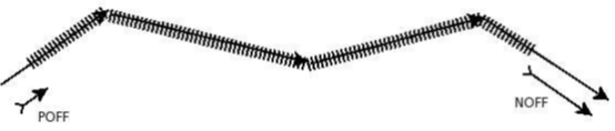
- A Positive OFFset (POFF) is used to locate the precise start of a location. The POFF defines the distance between the start of the location reference path and the start of the location.
- A Negative OFFset (NOFF) is used to locate the precise end of the location. It also defines the distance between the end of the location and the end of the location reference path.
The next image shows the positive and the negative offset:
The composition of an LRP depends on the location type. The location type Linear uses different types of LRPs:
- The First LRPdescribes the start line of the linear location (mandatory).
- The Last LRP refers to the end line of the location (mandatory).
- An Intermediate LRP may be added to the list of LRPs if the encoder decides to mark additional lines along the location path (optional). These additional LRPs act as a guide for the decoder to reconstruct the location.
To add more precision to the location, the location reference may contain information about positive and negative offsets.
Building blocks used are:
- First LRP: COORD, BEAR, FRC, FOW, LFRCNP, DNP
- Intermediate LRP: COORD, BEAR, FRC, FOW, LFRCNP, DNP
- Last LRP: COORD, BEAR, FRC, FOW
- POFF
- NOFF